
Adaptive vertical routing method based on network on chip and routing unit

A network-on-chip, self-adaptive technology, applied in data exchange networks, electrical components, digital transmission systems, etc., can solve the problems of increased transmission path length, long top-layer heat dissipation path, and increased bottom burden, etc., to achieve transmission path length reduction, The effect of reducing transmission burden and reducing redundant vertical transmission

Active Publication Date: 2017-07-14
NAT UNIV OF DEFENSE TECH
View PDF9 Cites 4 Cited by
  • Summary
  • Abstract
  • Description
  • Claims
  • Application Information

AI Technical Summary

Problems solved by technology

[0005] At present, in network-on-chip transmission, it is usually used to fix all the transmissions on the bottom layer before reaching congestion. Vertical transmission leads to increased delay. For example, when both the source node and the destination node are at the top layer, if the above routing method is used to route downwards, a large number of redundant vertical transmissions will be added, which will greatly increase the length of the transmission path, which not only increases the delay but also increases the delay. Increased the burden on the bottom; if the source node is on the lower layer and the destination node is on the top layer, if the above routing method is used to transmit vertically and then horizontally, the transmission will appear on the top layer, which will make the heat dissipation path of the top layer long and cause the problem of overheating

Method used


Image

  • Adaptive vertical routing method based on network on chip and routing unit
  • Adaptive vertical routing method based on network on chip and routing unit
  • Adaptive vertical routing method based on network on chip and routing unit

Examples


Embodiment Construction

[0041] The present invention will be further described below in conjunction with the accompanying drawings and specific preferred embodiments, but the protection scope of the present invention is not limited thereby.

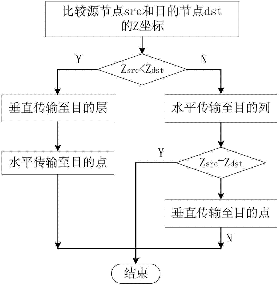
[0042] The self-adaptive vertical routing method based on the on-chip network of the present invention includes, when transmitting data from the source node to the destination node, determining the direction of the next transmission node each time according to the relationship between the current node coordinate position and the destination node coordinate position of the transmission data, So that when the source node is at the upper layer of the destination node, the source node is first transmitted in the vertical direction and then horizontally transmitted to the destination node, and when the source node is at the lower layer of the destination node, the source node is first transmitted in the horizontal direction and then horizontally It is transmitted to t...


PUM


Abstract

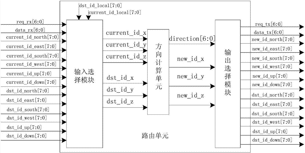
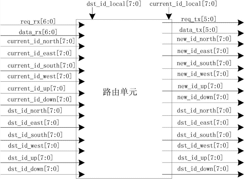
The invention discloses an adaptive vertical routing method based on a network on chip and a routing unit. The routing method comprises steps of determining the direction of the next transmission node based on the relationship between the current node coordinate position and the destination node coordinate position of the transmitted data each time when the data are transmitted from the source node to the destination node, so that when the source node is at the upper position of the destination node, transmission is firstly performed in the vertical direction and then in the horizontal direction, when the source node is in the lower position of the destination node, transmission is firstly performed in the horizontal direction and then in the vertical direction, and when the source node and the destination node are in the same layer, transmission is directly performed in the horizontal direction. The routing unit comprises an input / output interface unit, an input / output selection unit and a direction calculation unit. The adaptive vertical routing based on the network on chip is achieved, the implementation method is simple, the transmission time is less, the transmission congestion is avoided, and the temperature control and the flexible transmission are realized at the same time.

Description

technical field [0001] The invention relates to the technical field of microprocessor on-chip network transmission, in particular to an adaptive vertical routing method and a routing unit based on an on-chip network. Background technique [0002] With the development of modern technology, the network-on-chip structure has gradually become a popular structure for VLSI design, but this structure also produces a large number of temperature problems while increasing performance, including reducing the global interconnection line in order to improve transmission efficiency. The length, and the lower power consumption provides greater bandwidth, the shortening of interconnect lines and the increase of traffic speed up the generation of heat, etc.; at the same time, due to the constraints of area and timing, the arrangement of many cores has become more Tight, block stacking makes heat dissipation more difficult. At the same time, the 3D-NoC structure makes the heat dissipation pat...

Claims


Application Information

Patent Timeline
IPC IPC(8): H04L12/715H04L12/733H04L12/751H04L12/933H04L45/02H04L45/122
CPCH04L45/02H04L45/04H04L45/122H04L49/109
Inventor 彭元喜王建之李勇万江华雷元武鲁建壮孙书为刘胜王耀华田甜彭浩徐恩张榜
Owner NAT UNIV OF DEFENSE TECH
Learn More