Active two-phase loop and phase change heat storage compound thermal control system

A technology of phase change thermal storage and thermal control system, which is applied in cooling/ventilation/heating transformation, modification with liquid cooling, electrical components, etc. Poor matching performance, reduced reliability of electronic devices and other problems, to achieve the effect of enhancing dynamic matching performance, eliminating fatal danger, and reducing circulation flow

Inactive Publication Date: 2017-07-14
TSINGHUA UNIV
View PDF4 Cites 18 Cited by
  • Summary
  • Abstract
  • Description
  • Claims
  • Application Information

AI Technical Summary

Problems solved by technology

Excessive temperature will lead to a series of irreversible damages such as mechanical failure, corrosion failure and electrical failure of electronic devices. In addition, for this type of electronic equipment, its heat consumption will change dynamically with the application of the client, and excessive temperature changes will not only Have a huge impact on its performance and cause a reduction in the reliability of electronic devices
[0003] Although the traditional air-cooled radiator has a simple structure, it is increasingly difficult to meet the heat dissipation requirements of high heat flux electronic devices, and at the same time, it has poor dynamic matching performance with the actual heat consumption of el...

Method used


Image

  • Active two-phase loop and phase change heat storage compound thermal control system
  • Active two-phase loop and phase change heat storage compound thermal control system
  • Active two-phase loop and phase change heat storage compound thermal control system

Examples


Embodiment Construction

[0021] Below in conjunction with accompanying drawing, structure, principle and specific implementation of the present invention will be further described:

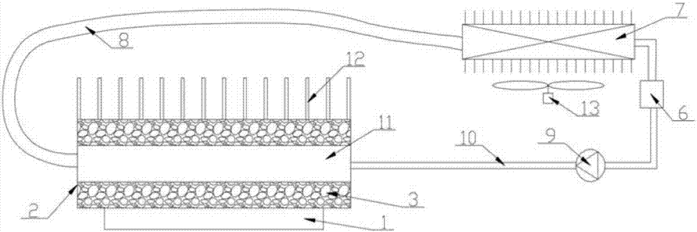
[0022] Such as figure 1 As shown, the present invention provides an active two-phase loop combined with phase change heat storage thermal control system, mainly including heat absorber 2, heat storage material 3, liquid storage device 6, condenser 7, steam pipeline 8. Driving device 9, liquid pipeline 10, evaporation chamber 11, fins 12 and fan 13; the heat absorber 2 is composed of heat conduction shell, evaporation chamber 11, heat storage material 3 and fins located on the heat conduction shell 12 packaged into an integrated structure; the outlet of the evaporation chamber 11 is connected to the inlet of the condenser 7 through the steam pipeline 8, and the outlet of the condenser 7 is connected to the liquid reservoir 6 and the driving device 9 through the liquid pipeline 10 in turn, and finally the outlet through the...


PUM


Abstract

The invention provides an active two-phase loop and phase change heat storage compound thermal control system, which belongs to the technical field of heat radiation and cooling. The system mainly comprises a heat absorber, a reservoir, a condenser, a steam line, a drive device, a liquid line and a blower fan. The heat absorber is of an integrated structure which is formed by packaging a head conducting housing, an evaporation chamber, a heat storage material and fins. The outlet of the evaporation chamber is communicated with the inlet of the condenser through the steam line, and the outlet of the condenser is connected with the reservoir and the drive device in sequence through the liquid line, and finally accesses to the inlet of the evaporation chamber, so as to form an enclosed loop. When the calorific value is small, heat can be absorbed by the heat storage material and radiated through the fins, so as to limit or delay the temperature rise; when the calorific value is larger, the drive device is started to operate the active two-phase loop. Specifically, when the heat changes dynamically or in a pulsed manner, the system maintains the good temperature control of the electronic chip or equipment, and has advantages of strong heat dissipation capacity, compact structure, safe temperature control, strong applicability, wide application range and the like.

Description

technical field [0001] The invention relates to a thermal control system combined with an active two-phase loop and phase change heat storage, belonging to the technical field of heat dissipation and cooling. Background technique [0002] The rapid development of electronic technology has brought revolutionary changes to human life. At the same time, the heat consumption of electronic devices such as laser devices, LED equipment, electronic chips and equipment has increased sharply, and the cooling and heat dissipation problems have become increasingly prominent. Excessive temperature will lead to a series of irreversible damages such as mechanical failure, corrosion failure and electrical failure of electronic devices. In addition, for this type of electronic equipment, its heat consumption will change dynamically with the application of the client, and excessive temperature changes will not only It has a huge impact on its performance and causes a reduction in the reliabil...

Claims


Application Information

Patent Timeline
IPC IPC(8): H05K7/20
CPCH05K7/2029H05K7/20309H05K7/20318H05K7/20381
Inventor 史琳马跃征陈静冯乐军
Owner TSINGHUA UNIV
Why Eureka
Try Eureka