
Under-floor air supply data center refrigeration system

A data center refrigeration and data technology, which is applied in ventilation systems, space heating and ventilation, space heating and ventilation details, etc., can solve the problems of increased energy consumption of air-conditioning fans, reduce cooling energy consumption, and avoid hot and cold air Effect of mixing and increasing static pressure

Active Publication Date: 2017-07-18
SHANGHAI ENG RES CENT FOR BROADBAND TECH & APPL
View PDF2 Cites 5 Cited by
  • Summary
  • Abstract
  • Description
  • Claims
  • Application Information

AI Technical Summary

Problems solved by technology

[0004] In view of the above-mentioned shortcomings of the prior art, the purpose of the present invention is to provide a downflow data center refrigeration system, which is used to solve the problem of increased energy consumption of air-conditioning fans due to the increase in the power density of the cabinets in the prior art

Method used


Image

  • Under-floor air supply data center refrigeration system
  • Under-floor air supply data center refrigeration system
  • Under-floor air supply data center refrigeration system

Examples


Embodiment 1

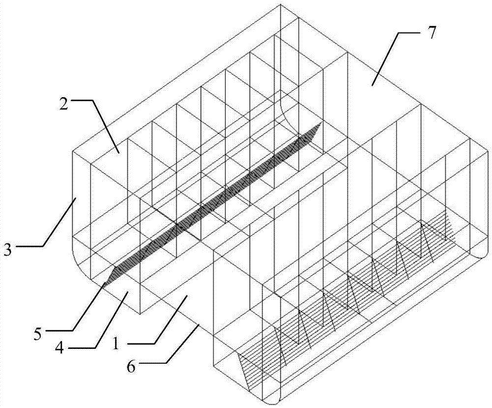
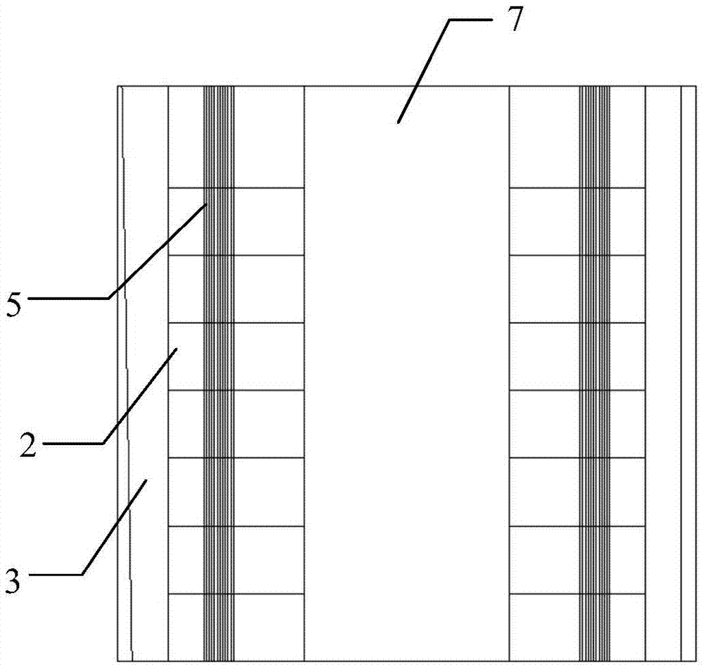
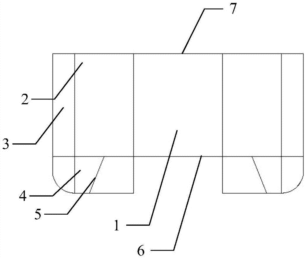
[0045] like figure 1 As shown, the cooling system of the downflow data center in this embodiment includes a cold aisle 1 surrounded by two rows of cabinets 2 arranged face to face at the air inlet ends, an aisle door, a raised through-hole floor 6, and a top sealing plate 7; That is to say figure 1 The front end of the intercooling aisle 1 is provided with the passage door, and a row of cabinets 2 are respectively provided on both sides of the cold aisle 1, and a raised through-hole floor 6 is provided below the cold aisle 1, and a top sealing plate 7 is provided above The length of the cold aisle 1 is not less than the length of the single-row cabinet 2, and the width of the cold aisle 1 is not less than twice the depth of the cabinet 2; preferably, the raised through-hole floor 6 and the cold aisle 1 There is a sealed connection between the bottoms, and a sealed connection between the top sealing plate 7 and the top of the cold aisle 1 . Further preferably, the width of th...

Embodiment 2

[0052] The difference between this embodiment and the first embodiment is that the top sealing plate 7 is also provided with a movable skylight 8, and when a fire occurs, the movable skylight 8 is fully opened, and at the same time, the fire-fighting gas enters the interior of the cold aisle for gas fire extinguishing. For details, please refer to the attached Figure 4 ~ Figure 5 .

[0053] To sum up, in the downflow data center refrigeration system of the present invention, the hot air discharged from the air outlet end of the cabinet enters the air return device, and then is sent to the return air pipe under the cabinet by the air return device. One side of the air return pipe is connected with the air return device, and the other side leads to the raised through-hole floor, and a heat exchanger is installed inside the air return pipe. The heat exchanger cools the hot air in the return air duct, and the cooled cold air enters under the raised through-hole floor through the...


PUM


Abstract

The invention provides an under-floor air supply data center refrigeration system. The under-floor air supply data center refrigeration system comprises two rows of cabinets, the air inlet ends of which are arranged in a face-to-face manner; air return devices, which are connected with the air outlet ends of the cabinets; air return ducts provided with built-in heat exchangers; a machine room elevated through hole floor; and a cooling channel formed by the cabinets, a channel door, the elevated through hole floor, and a top part closing plate in an encircled manner. The hot air exhausted by the air outlet ends of the cabinets are delivered by the air return devices to the heat exchangers for cooling. The heat exchangers are disposed in the air return ducts, and one side of each of the air return ducts is connected with the corresponding air return device, and the other side of each of the air return ducts is connected with the lower part of the elevated through hole floor. The cooled air enters the lower part of the floor, and is delivered to the cooling channel by the through hole floor after being mixed and stabilized. The cool air in the cooling channel is sucked in by the cabinets, and then is exhausted by the cabinets to complete heat dissipation circulation. The under-floor air supply data center refrigeration system is advantageous in that energy loss of a draught fan on an end of an air conditioner is saved, and problems of common under-floor air supply systems such as non-uniform air supply in the length direction of the cooling channel, two fast bottom air supply speed, small air inlet quantity of servers on the lower parts of the cabinets, and easy generation of local hot spots are improved, and therefore the internal temperature of the cabinets is reduced, and the integrated heat dissipation efficiency of the cabinets is improved.

Description

technical field [0001] The invention relates to a data center refrigeration system, in particular to a downflow data center refrigeration system. Background technique [0002] The data center's demand for energy is ultimately reflected in the demand for electrical energy. At present, the energy consumption of IT equipment only accounts for 30% of the energy consumption of the entire data center, while the energy consumption of cooling equipment accounts for 50%-60%. The cooling system is the largest energy consumer in the data center computer room. Recently, large-scale, high-density, and data-concentrated data centers are becoming more and more popular, and the heat dissipation problem of high-density server rooms is becoming more and more difficult to solve. The use of traditional precision air-conditioning systems presents a huge energy consumption, and the PUE value remains high. status. Therefore, the energy saving of the air conditioning system is the core of the ov...

Claims


Application Information

Patent Timeline
Patent Type & Authority Applications(China)
IPC IPC(8): H05K7/20F24F7/06F24F13/30
CPCF24F7/06F24F13/30H05K7/20745
Inventor 郑贤清葛昌荣王启旻
Owner SHANGHAI ENG RES CENT FOR BROADBAND TECH & APPL
Learn More