Underwater separation device with pre-separation pipeline and underwater separation method thereof

A pre-separation tube and separation device technology, applied in separation methods, dispersed particle separation, chemical instruments and methods, etc., can solve the problems of reduced separation efficiency, droplet breakage, entrainment, etc., to improve gas-liquid separation efficiency and improve efficiency , the effect of improving work efficiency

Inactive Publication Date: 2017-07-21
CHINA NAT OFFSHORE OIL CORP +1
View PDF2 Cites 1 Cited by
  • Summary
  • Abstract
  • Description
  • Claims
  • Application Information

AI Technical Summary

Problems solved by technology

[0003] The blade centrifugal separator is a high-efficiency separation method, but the centrifugal separator with blades has a higher separator efficiency when the droplets are relatively small, but when the droplets are large and the liquid content is relatively large, Droplet breakage, entrainment, etc. will occur, resulting in reduced separation efficiency
Therefore, the existing centrifugal separator with blades is suitable for the situation of stable working conditions, but not suitable for the current situation of large fluctuations in working conditions of deep-water natural gas fields

Method used


Image

  • Underwater separation device with pre-separation pipeline and underwater separation method thereof
  • Underwater separation device with pre-separation pipeline and underwater separation method thereof

Examples


Embodiment Construction

[0021] The present invention will be described in detail below in conjunction with the accompanying drawings and embodiments.

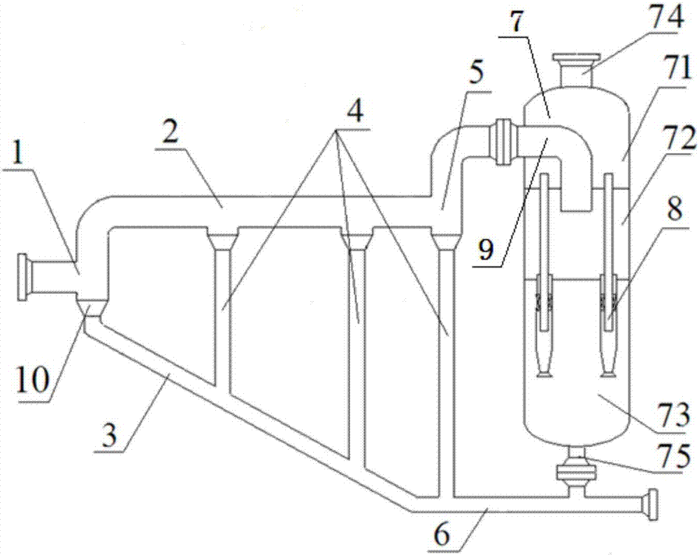
[0022] Such as figure 1 As shown, the present invention provides an underwater separation device with a pre-separation pipeline, which includes a pre-separation pipeline and a centrifugal separator; wherein, the pre-separation pipeline includes an inlet tee 1, a gas phase main pipe 2, a liquid Phase inclined pipe 3, downcomer 4 and outlet tee 5; the first port of the inlet tee 1 is used as the inlet of the pre-separation pipeline, and the second port of the inlet tee 1 is connected with the inlet end of the gas phase main pipe 2, And the gas phase main pipe 2 is arranged horizontally; the third port of the inlet tee 1 is connected to the inlet end of the liquid phase inclined pipe 3, and the liquid phase inclined pipe 3 is arranged obliquely below the gas phase main pipe 2; A plurality of downcomers 4 are arranged, and the gas phase main pipe 2 is co...


PUM


Abstract

The invention discloses an underwater separation device with a pre-separation pipeline and an underwater separation method. The device comprises the pre-separation pipeline and a centrifugal separator, wherein the pre-separation pipeline comprises a main gas phase pipe, an inclined liquid phase pipe and liquid falling pipes; the main gas phase pipe comprises an inlet condensate section, a horizontal section and an outlet condensate section which are connected in sequence; the inlet condensate section extends downwards relatively to the horizontal section; the outlet condensate section extends upwards relatively to the horizontal section; the inclined liquid phase pipe is arranged below the main gas phase pipe in an inclined manner; the inlet end of the inclined liquid phase pipe is communicated with the bottom of the inlet condensate section; the liquid falling pipes are respectively arranged between the bottom of the horizontal section and the inclined liquid phase pipe and between the bottom of the outlet condensate section and the inclined liquid phase pipe; the centrifugal separator comprises a pressure vessel tank and a plurality of centrifugal separation pipes; the pressure vessel tank is divided into a gas discharging chamber, a gas inlet chamber, and a liquid discharging chamber; the plurality of centrifugal separation pipes for communicating the gas discharging chamber and the liquid discharging chamber; and a gas discharging opening of the outlet condensate section is communicated with the gas inlet chamber.

Description

technical field [0001] The invention relates to a device and method for underwater natural gas-liquid separation, in particular to an underwater separation device and method with a pre-separation pipeline. Background technique [0002] With the development of offshore oil technology, underwater natural gas fields have been continuously discovered and developed. In the development process of underwater, especially deep-water natural gas fields, problems such as high water content or high condensate content are often encountered, which is accompanied by flow safety risks in the transportation process. When the liquid content is small, hydrate inhibitors such as ethylene glycol can be injected, but when the liquid volume is relatively large, the injection of hydrate inhibitors cannot meet the flow safety requirements, which requires other methods to ensure the safety of deep-water gas fields. Mobile Security Risk. Among them, underwater separation is one of the measures. [...

Claims


Application Information

Patent Timeline
IPC IPC(8): B01D45/02B01D45/08B01D45/12C10L3/10
CPCB01D45/02B01D45/08B01D45/12C10L3/101C10L3/106
Inventor 刘永飞李清平姚海元秦蕊程兵庞维新
Owner CHINA NAT OFFSHORE OIL CORP
Why Eureka
Try Eureka