
Automatic assembly machine of gas stove ignition device, and control method thereof

A technology of ignition device and gas stove, which is applied in the direction of manufacturing tools, metal processing, metal processing equipment, etc., can solve the problems of poor product quality stability and low efficiency, and achieve the effect of good product quality stability and high efficiency

Inactive Publication Date: 2017-07-21
ZHEJIANG UNIVERSITY OF SCIENCE AND TECHNOLOGY +1
View PDF10 Cites 10 Cited by
  • Summary
  • Abstract
  • Description
  • Claims
  • Application Information

AI Technical Summary

Problems solved by technology

This kind of assembly method has low efficiency and poor product quality stability, and realizes an equipment that can complete the automatic tightening assembly of the gas ignition device and the intake pipe, the calibration of the outlet flow and the air tightness detection of the assembly

Method used


Image

  • Automatic assembly machine of gas stove ignition device, and control method thereof
  • Automatic assembly machine of gas stove ignition device, and control method thereof
  • Automatic assembly machine of gas stove ignition device, and control method thereof

Examples


Embodiment 1

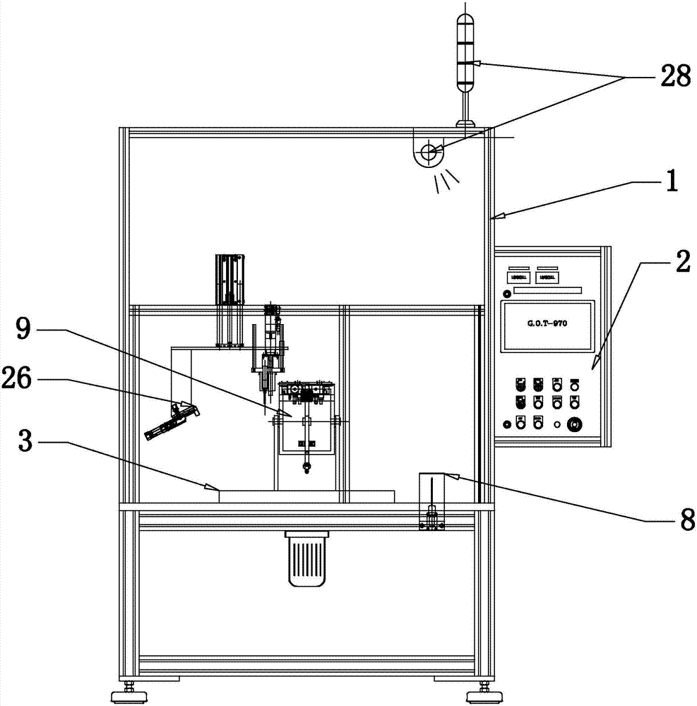
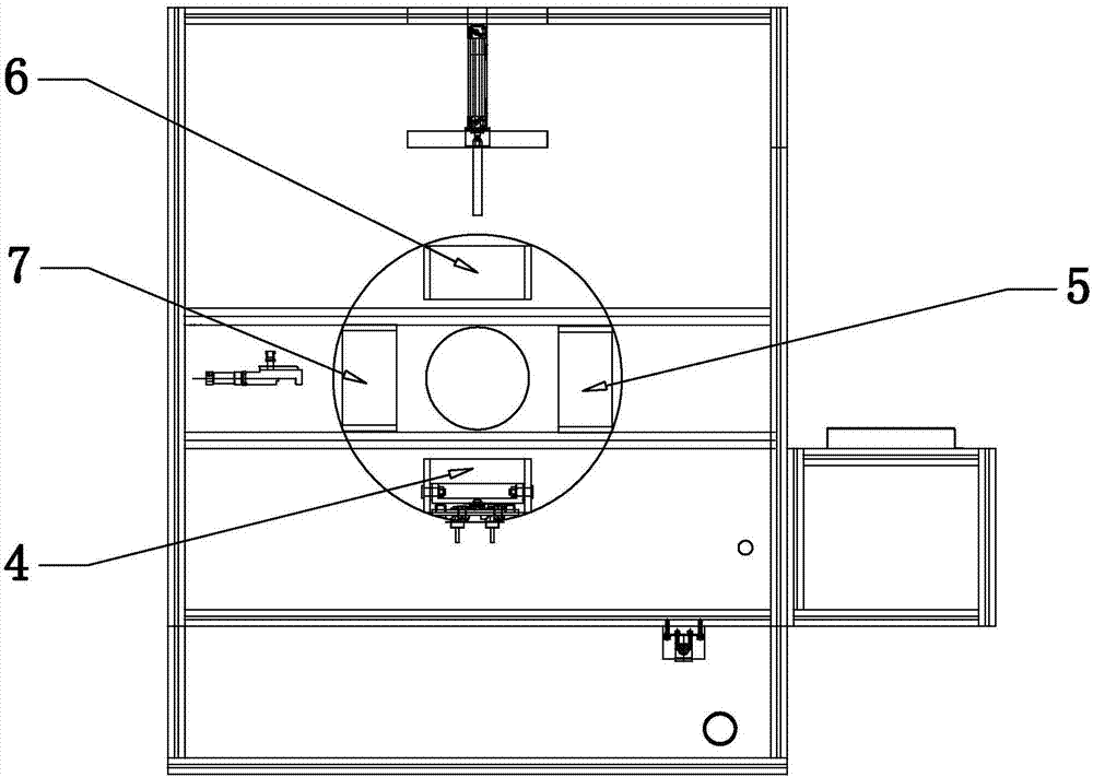
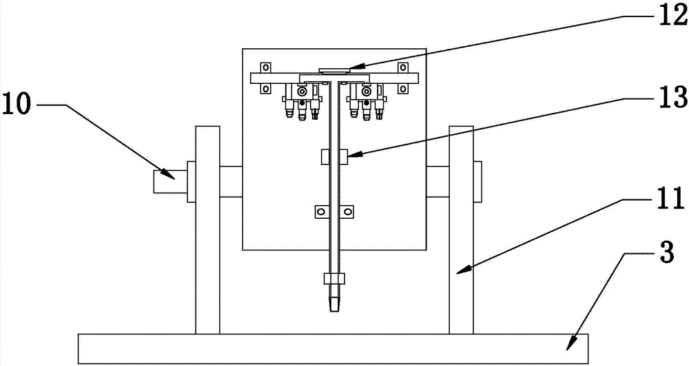
[0031] Embodiment one: if Figure 1-8 As shown, the present invention is an automatic assembly machine for a gas stove ignition device, comprising a frame 1 and a control unit 2, the frame 1 is provided with a working platform, and the center of the working platform is provided with a rotating device 3, and the rotating device 3 The four sides are respectively provided with a loading and unloading station 4, a tightening station 5, a flow regulating station 6 and an air tightness testing station 7 in sequence, and the frame 1 is provided with a start switch 8, a control unit 2 and a power system , the start switch 8 is a start button, the rotating device 3, the loading and unloading station 4, the tightening station 5, the flow regulating station 6 and the air tightness detection station 7 are all connected to the power system and the control unit 2, the The start switch 8 is connected to the control unit 2 . The control unit is connected with a paint spotting and scanning wo...

Embodiment 2

[0045] Embodiment two: if Figure 1-8 As shown, the present invention is an automatic assembly machine for a gas stove ignition device, such as Figure 1-8 As shown, the present invention is an automatic assembly machine for a gas stove ignition device, comprising a frame 1 and a control unit 2, the frame 1 is provided with a working platform, and the center of the working platform is provided with a rotating device 3, and the rotating device 3 The four sides are respectively provided with a loading and unloading station 4, a tightening station 5, a flow regulating station 6 and an air tightness testing station 7 in sequence, and the frame 1 is provided with a start switch 8, a control unit 2 and a power system , the rotating device 3, the loading and unloading station 4, the tightening station 5, the flow regulating station 6 and the air tightness detection station 7 are all connected to the power system and the control unit 2, and the start switch 8 is connected to the contr...


PUM


Abstract

An automatic assembly machine of a gas stove ignition device comprises a rack and a control unit. The rack is provided with a working platform of which the center is provided with a rotary device, and four sides of the rotary device are provided with feeding and blanking stations, tightening stations, flow adjusting stations and airtightness detecting stations in order respectively; the rack is provided with a start switch, the control unit and a power system, and the rotary device, the feeding and blanking stations, the tightening stations, the flow adjusting stations and the airtightness detecting stations are all connected to the power system and the control unit; and the start switch is connected to the control unit. In the invention, automatic assembly and detection of an ignition device are achieved, without manual assembly required, and the assembly efficiency is improved; quality inspection is performed through equipment, so that the product quality stability is improved.

Description

technical field [0001] The invention relates to the technical field of production of gas stove ignition devices, in particular to an automatic assembly machine for gas stove ignition devices. Background technique [0002] The assembly of the ignition device and the intake pipe of the double-burner gas stove is a key process in the assembly of the gas stove. At present, most of them use manual assembly and manual detection of air tightness. This assembly method has low efficiency and poor product quality stability. For example, the Chinese patent with the publication number CN103388835 discloses an ignition electronics, and particularly relates to a casing of a gas stove igniter, a gas stove igniter and an assembly process of the gas stove igniter. The invention provides the following technical solutions: a casing of a gas stove igniter, including a casing and a wire connection pipe vertically arranged to the casing, a cavity for placement is provided in the casing, and the ...

Claims


Application Information

Patent Timeline
Patent Type & Authority Applications(China)
IPC IPC(8): B23P19/06B23P19/00B23P19/10
CPCB23P19/004B23P19/069B23P19/105
Inventor 庞茂吴瑞明李强
Owner ZHEJIANG UNIVERSITY OF SCIENCE AND TECHNOLOGY
Learn More