
Safe box automatic welding and polishing system
An automatic welding and safe technology, applied in other manufacturing equipment/tools, manufacturing tools, etc., can solve the problems of complex fixture structure, high labor intensity of workers, low production efficiency, etc., achieve low labor intensity, save blank clamping and The effect of transportation and waste reduction
- Summary
- Abstract
- Description
- Claims
- Application Information
AI Technical Summary
Problems solved by technology
Method used
Image

Examples
Embodiment 1
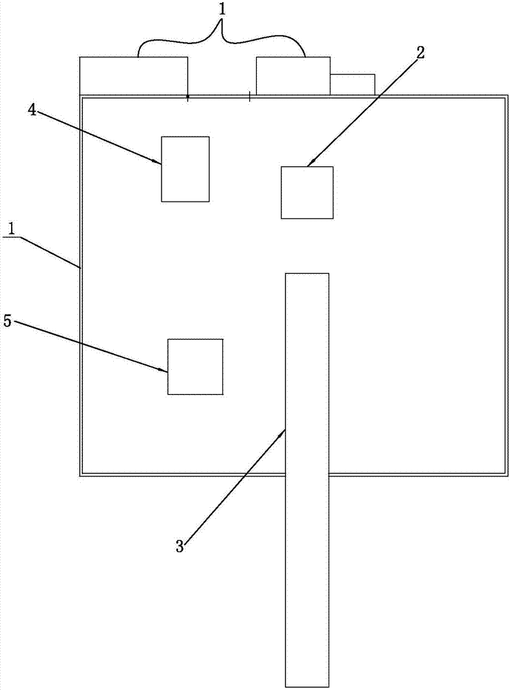
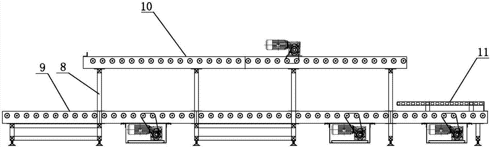
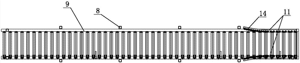
[0044] Such as Figure 1-9 As shown, a safe automatic welding and grinding system includes a control mechanism 1 and a six-axis welding robot 2 fixed on the ground. It also includes a conveying device 3, a grinding device 4 and a six-axis handling robot 5 fixed on the ground. The working range of the working arm of the six-axis handling robot 5 partially overlaps the working range of the working arm of the six-axis welding robot 2, and one end of the conveying equipment 3 is located within the working range of the working arm of the six-axis handling robot 5, and the grinding equipment 4 is also located Within the working range of the six-axis handling robot 5 working arm, the six-axis handling robot 5 working arm is provided with a clamp 6 for clamping the safe blank; the clamp 6 includes a platform 21, a cylinder 22 and a chuck 23. The plane is connected to the working arm of the six-axis handling robot 5 through the connecting block 24, half of the chuck 23 is fixed on one ...
Embodiment 2
[0055] The grinding equipment 4 is an abrasive belt machine, and the abrasive belt machine includes an abrasive belt working wheel 16 and a body 17. The abrasive belt operating wheel 16 is located at the upper end of the body 17, and waste material is provided directly below the abrasive belt operating wheel 16. Collection box 18; the included angle between the abrasive belt 19 of the abrasive belt machine and the vertical direction is 20°.
[0056] The outer peripheral surface of the abrasive belt working wheel 16 is provided with several evenly distributed strip-shaped grooves 20, the strip-shaped grooves 20 are arranged obliquely, and the strip-shaped grooves 20 and the abrasive belt working wheel 16 The included angle between the axes is 10°; the depth of the elongated groove 20 is 4mm, and the width is 4mm.
[0057] All the other are the same as the first embodiment.
Embodiment 3
[0059] The grinding equipment 4 is an abrasive belt machine, and the abrasive belt machine includes an abrasive belt working wheel 16 and a body 17. The abrasive belt operating wheel 16 is located at the upper end of the body 17, and waste material is provided directly below the abrasive belt operating wheel 16. Collection box 18; the included angle between the abrasive belt 19 of the abrasive belt machine and the vertical direction is 60°.
[0060] The outer peripheral surface of the abrasive belt working wheel 16 is provided with several evenly distributed strip-shaped grooves 20, the strip-shaped grooves 20 are arranged obliquely, and the strip-shaped grooves 20 and the abrasive belt working wheel 16 The included angle between the axes is 50°; the depth of the elongated groove 20 is 8mm, and the width is 6mm.
[0061] All the other are the same as the first embodiment.
PUM
 Abstract
Description
Claims
Application Information