Building cleaning system and cleaning method

A technology for cleaning systems and buildings, applied in the field of systems for cleaning the outer walls of buildings, can solve the problems of bouncing off, limited adsorption force, slow speed, etc., and achieve the effects of reducing the shaking space, long service life and wide application range

Inactive Publication Date: 2017-07-21
盛富春
View PDF2 Cites 3 Cited by
  • Summary
  • Abstract
  • Description
  • Claims
  • Application Information

AI Technical Summary

Problems solved by technology

[0002] The building cleaning equipment in the prior art is mainly divided into two types according to the installation method when it is used: one is the rope hoisting type, and its defect is that the rope is a flexible part. When cleaning the outer wall of the building, the cleaning equipment must be subjected to a The horizontal reverse force on the outer wall of the building, and the greater the cleaning force, the greater the reverse force. Since the hoisting rope cannot help the cleaning device withstand the horizontal force from the outer wall of the building, the distance between the cleaning device and the outer wall The cleaning power cannot reach the ideal value, and sometimes the phenomenon of bouncing and detachment occurs, resulting in poor cleaning effect
The second is the adsorption walking type. This type of cleaning device is adsorbed on the outer wall of the building through the suction cup device. The disadvantages are: 1. The suction force that the suction cup can provide is limited, and the cleaning effect is not ideal; It has high requirements, narrow scope of application, and poor practicability; 3. The movement of the suction cup can not be continuous and the speed is slow, resulting in low work efficiency
[0003] On the other hand, only one cleaning module is currently used to clean buildings, which is inefficient

Method used


Image

  • Building cleaning system and cleaning method
  • Building cleaning system and cleaning method
  • Building cleaning system and cleaning method

Examples


Embodiment Construction

[0023] The technical scheme of the present invention is described in detail below in conjunction with accompanying drawing:

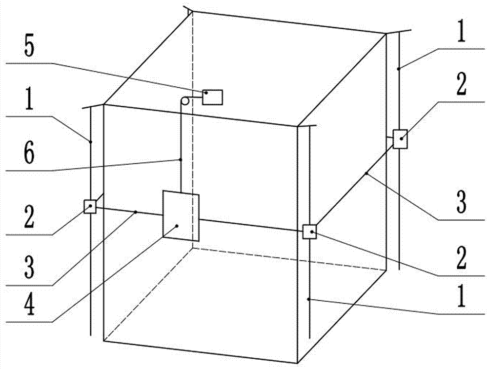
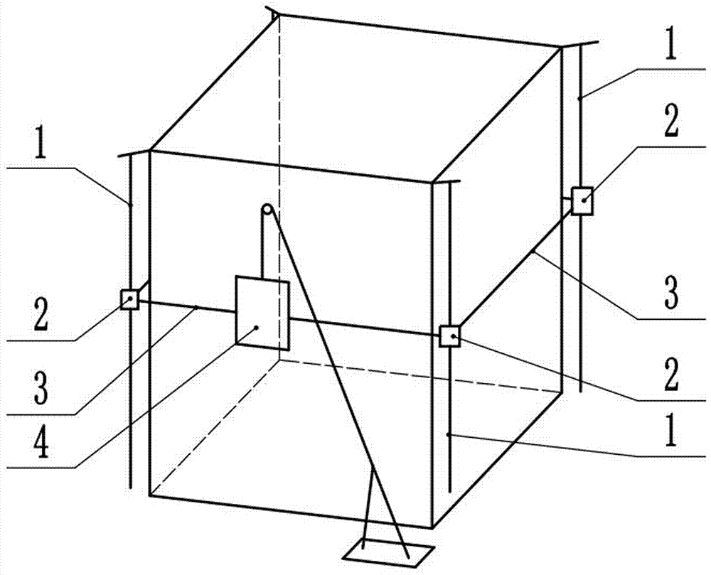
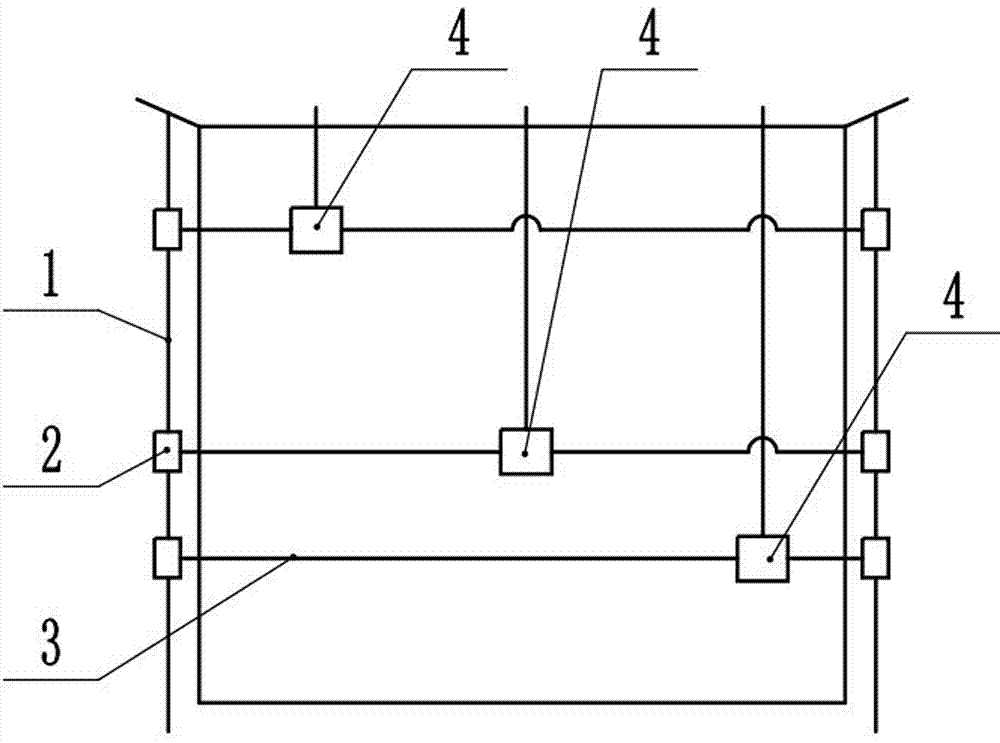
[0024] A building cleaning system comprising such as figure 1 The lifting device for installation on the building and the cleaning module 4 connected with the lifting device for cleaning the outer wall of the building; the cleaning module 4 moves up and down under the drive of the lifting device or autonomous power: the The lifting device includes a retractable device 5 installed on the building platform. The retractable device 5 includes a pulley and a tractor. The lifting device also includes a vertical rope 6. One end of the vertical rope 6 is connected to the tractor, and the other end is connected to the cleaning module 4, so that the cleaning module 4 moves up and down under the traction of the tractor; the cleaning module 4 is an automatic cleaning device such as a cleaning robot for scrubbing the outer wall of the building, and can also be a han...


PUM


Abstract

The invention discloses a building cleaning system and cleaning method. The cleaning system comprises lifting devices and cleaning modules (4) connected with the lifting devices, and the cleaning modules (4) are driven by the lifting devices to move up and down; and the cleaning system further comprises annular ropes (3) arranged on the outer wall of a building in a sleeving mode, and the annular ropes (3) are connected with the cleaning modules (4). According to the cleaning method, the cleaning modules (4) are adopted to conduct cleaning simultaneously, and a computer device is used for coordinated controlling to avoid interference. According to the building cleaning system and cleaning method, the annular ropes (3) and the cleaning modules (4) are subjected to the reverse force from the building, so that the cleaning modules (4) always maintain sufficient contact force with the building, and the desired cleaning effect can be achieved; and meanwhile, the cleaning efficiency is improved greatly through multi-module coordinated cleaning.

Description

technical field [0001] The invention relates to a system for cleaning the outer wall of a building, which can be used for cleaning the outer wall of a building or other occasions requiring high-altitude vertical operations; meanwhile, it also relates to a method for cleaning a building. Background technique [0002] The building cleaning equipment in the prior art is mainly divided into two types according to the installation method when it is used: one is the rope hoisting type, and its defect is that the rope is a flexible part. When cleaning the outer wall of the building, the cleaning equipment must be subjected to a The horizontal reverse force on the outer wall of the building, and the greater the cleaning force, the greater the reverse force. Since the hoisting rope cannot help the cleaning device withstand the horizontal force from the outer wall of the building, the distance between the cleaning device and the outer wall The cleaning power of the cleaning machine ca...

Claims


Application Information

Patent Timeline
Patent Type & Authority Applications(China)
IPC IPC(8): E04G23/00
CPCE04G23/002
Inventor 盛富春
Owner 盛富春
Why Eureka
Try Eureka