Spraying direction adjustable inclined hole fuel injector adapter device
A technology of injection direction and fuel injector, which is applied to fuel injection devices, measuring devices, instruments, etc. to achieve good cooling effect and facilitate image processing and analysis.
- Summary
- Abstract
- Description
- Claims
- Application Information
AI Technical Summary
Problems solved by technology
Method used
Image

Examples
Embodiment Construction
[0028] In order to make the purpose, technical solutions and advantages of the embodiments of the present invention clearer, the technical solutions in the embodiments of the present invention will be clearly and completely described below in conjunction with the drawings in the embodiments of the present invention. Obviously, the described embodiments It is a part of embodiments of the present invention, but not all embodiments.
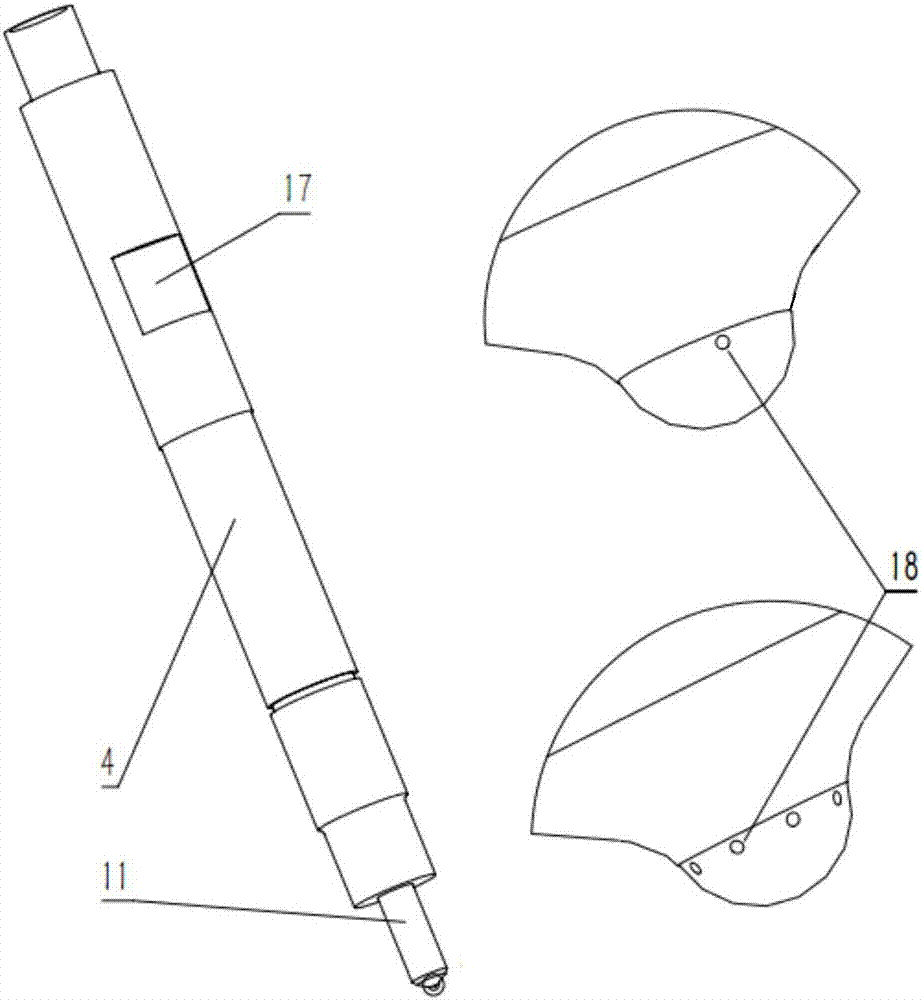
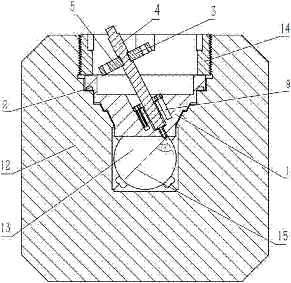
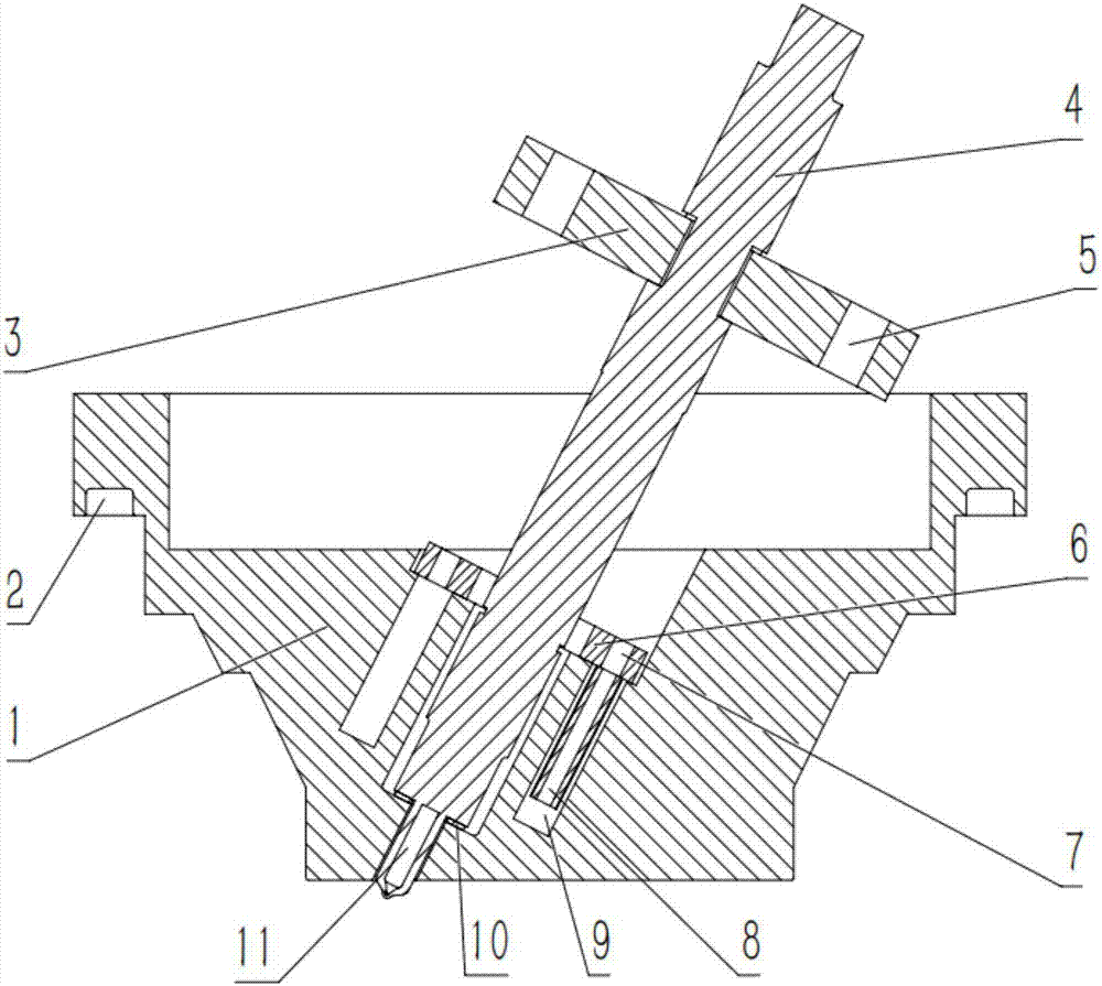
[0029] figure 1 It is the sectional view of the oblique hole fuel injector adapter device with adjustable injection direction of the present invention; as figure 1 As shown, the oblique-hole fuel injector adapter device with adjustable injection direction of the present invention includes a fuel injector adapter 1, an O-ring groove 2, an adjustable gland 3, a fuel injector 4, an arc groove 5, a cooling Water chamber cover 6, threaded hole 7, extension pipe 8, cooling water chamber 9, copper gasket 10 and fuel injection nozzle 11.
[0030] The fuel...
PUM
 Abstract
Description
Claims
Application Information
PatSnap Eureka turns technology decisions into work you can execute. Powered by our Innovation Knowledge Graph, it runs expert workflows across engineering, life sciences, materials and intellectual property. Get your review-ready output in minutes.


