Time test circuit and time test method

A technology for testing circuits and time, applied in the direction of electrical unknown time interval measurement, devices and instruments for measuring time interval, etc., can solve the problems of inclusions, circuit errors, long rising edge time of pulse signals, etc., so as to reduce the turnover time and avoid the impact , the effect of reducing power consumption

Inactive Publication Date: 2017-07-21
NINGBO UNIV
View PDF0 Cites 10 Cited by
  • Summary
  • Abstract
  • Description
  • Claims
  • Application Information

AI Technical Summary

Problems solved by technology

The trigger signal is directly selected as the propagation signal in the delay chain, because the rising edge time of the pulse signal as the trigger signal is relatively long, and at the same time, it is mixed with interference

Method used


Image

  • Time test circuit and time test method
  • Time test circuit and time test method

Examples


Embodiment Construction

[0021] The present invention will be further described in detail below in conjunction with the accompanying drawings and embodiments.

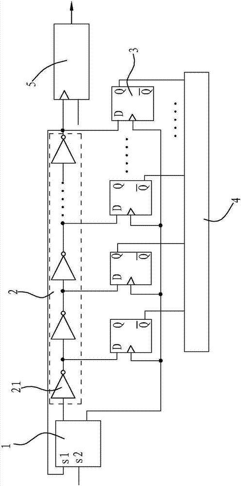
[0022] Such as figure 1 As shown, the time test circuit in this embodiment is characterized in that it includes a voltage comparator 1 , an oscillator 2 , a plurality of D latches 3 , a temperature encoder 4 and a counter 5 .

[0023] The voltage comparator 1 can be composed of a bias circuit, a differential amplifier, a common source amplifier, and a push-pull stage output circuit. Since the rising edge time of the signal output by the voltage comparator 1 is too long, the capacitance will be increased during delay propagation in the oscillator 2 The charging and discharging time will increase the delay time of the single gate delay unit 21 accordingly. Therefore, the step signal output by the voltage comparator 1 is divided to obtain a step signal with a shorter rising edge as the start of the time and the end of the time. Stop internal tra...


PUM


Abstract

The invention relates to a time test circuit. The time test circuit comprises a voltage comparator, an oscillator, a plurality of D latches, a temperature coder and a counter. The voltage comparator can output a pair of steeply rising step-function signals serving as internal transmission signals of the start time and the end time; the oscillator is a delay chain circuit formed by series connection of multiple levels of door delay units, and is connected with the voltage comparator and the counter respectively. Each level of door delay unit is connected with one D latch, the time end signal output end in the voltage comparator is connected with the clock signal input ends of the D latches respectively, and the signal output ends of the D latches are connected with the input end of the temperature coder. The time test circuit works, and the delay time t is calculated through the formula t=N*n*TLSB+n1*TLSB, wherein N refers to the count value of the counter, n refers to the total level number of the door delay units in the delay chain circuit, and TLSB refers to the delay time of one door delay unit. The time test circuit and a time test method can reduce the switching time of the signals in each level of door delay unit and reduce the power consumption.

Description

technical field [0001] The invention relates to the technical field of digital circuits, in particular to a time test circuit and a time test method. Background technique [0002] With the continuous development of integrated circuit size miniaturization, high-precision time test chips have become a research hotspot. The traditional direct counting method realizes time measurement by counting the frequency of the reference clock. When the clock frequency is GHz, its time measurement accuracy It has only reached the ns level, and its accuracy is greatly limited by the frequency of the reference clock, which cannot meet higher measurement accuracy. Then a time measurement method based on delay unit was proposed. The time start signal propagates in the delay chain. When the time end signal arrives, the position where the time start signal propagates is locked. The measured time can be obtained by calculating the number of delay chains. Its accuracy depends on the delay time of...

Claims


Application Information

Patent Timeline
IPC IPC(8): G04F10/00
CPCG04F10/00
Inventor 杨昊杨鸣苟欣田沐鑫曾宇乾
Owner NINGBO UNIV
Why Eureka
Try Eureka