Cooling device and method for cylindrical power battery pack

A power battery pack and cooling device technology, which is applied in the direction of secondary batteries, circuits, electrical components, etc., can solve the needs of power battery thermal management that is difficult to meet the high energy density, and it is difficult to take into account the simple and compact structure, weak air cooling capacity, etc. problem, to avoid the safety problem of the battery pack, the structure is simple, and the capillary limit is large.

Pending Publication Date: 2017-07-21
SOUTH CHINA UNIV OF TECH
View PDF10 Cites 11 Cited by
  • Summary
  • Abstract
  • Description
  • Claims
  • Application Information

AI Technical Summary

Problems solved by technology

The air cooling capacity is weak. With the continuous improvement of the energy density of power battery packs, air cooling will be difficult to meet the thermal management needs of power batteries with high energy density; liquid cooling has the possibility of liquid leakage; phase change material cooling not only needs to consider phase change The physical properties of the material should also take into account issues such as the packaging of the phase change material
Cylindrical power batteries are attracting more and more attention and favor due to the advantages of mature production lines, low cost, good heat dissipation in groups, good consistency, and good safety performance. How to better manage the battery heat of cylindrical power batteries It is very important. However, for a large-scale packaged power battery system, it is difficult to take into account the two aspects of simple and compact structure and good heat dissipation effect by using the above cooling methods.

Method used


Image

  • Cooling device and method for cylindrical power battery pack
  • Cooling device and method for cylindrical power battery pack
  • Cooling device and method for cylindrical power battery pack

Examples


Embodiment

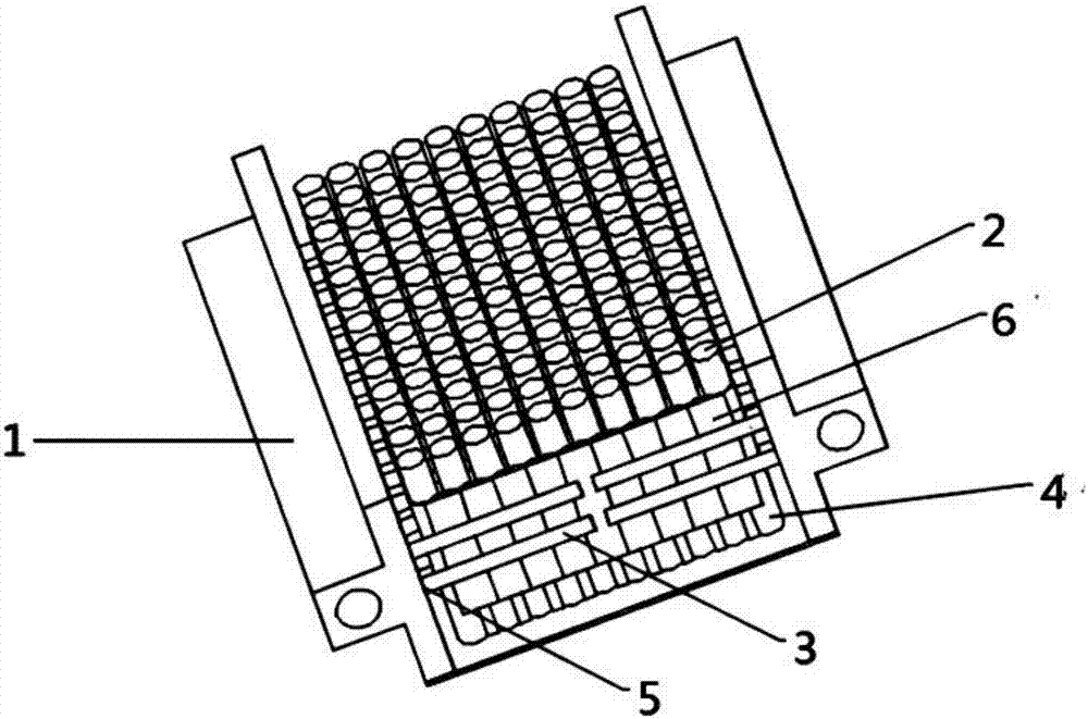
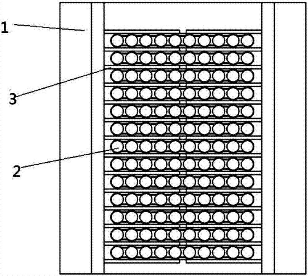
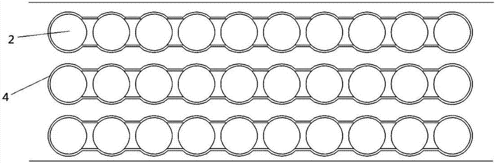
[0032] like Figures 1 to 5 shown. The invention discloses a cooling device for a cylindrical power battery pack, which includes a battery pack 2 and its cooling structure; the cooling structure includes a cooling passage 1 distributed on two sides of the battery pack 2 with a circulating cooling medium inside, and The heat generated by the battery pack 2 is transferred to the heat pipe 3 of the channel body of the cooling channel 1;

[0033] The heat generated by the battery pack 2 is indirectly transferred to the channel body of the cooling channel 1 through the heat pipe 3 , and the cooling medium circulating in the cooling channel 1 takes away the heat generated by the battery pack 2 .

[0034] The evaporating end 3-1 of the heat pipe 3 extends into the battery pack 2 and contacts the outer surface of the battery, and the condensing end 3-2 extends out of the battery pack and contacts the channel body. This structure realizes the indirect contact between the condensing e...


PUM


Abstract

The invention discloses a cooling device and method for a cylindrical power battery pack. The cooling device comprises a battery pack and a cooling structure thereof. The cooling structure includes a cooling channel which is distributed at two side faces of the battery pack and the inside of which is provided with a cyclically flowing cooling working medium, and heat pipes for transferring the heat generated by the battery pack to the channel body of the cooling channel; the heat generated by the battery pack is indirectly transferred to the channel body of the cooling channel through the heat pipes, and the heat generated by the battery pack is taken away by the cyclically flowing cooling working medium in the cooling channel. For the device, the heat pipes are adopted for heat-dissipation of the battery pack, the entire device is compact, small in floor space, flexible in layout, and easy for the connection between single cells. The cooling device has the advantages of simple structure, environment protecting and energy saving, easiness in installation and convenience in maintenance, so the problem of dissipation of the cylindrical power battery pack under different working conditions is solved to reduce the maximum temperature and the overall temperature difference of the battery pack, which has a good application prospect.

Description

technical field [0001] The invention relates to heat dissipation of components, in particular to a cooling device and method for a cylindrical power battery pack. Background technique [0002] Due to the advantages of high energy density, long cycle life, and high environmental protection performance, power batteries have become the power source of electric equipment such as electric vehicles and hybrid vehicles. However, the power battery will generate a lot of heat during charging and discharging, which will cause the temperature of the battery to rise. Especially for the entire power battery pack, the battery in the center has the worst heat dissipation effect, resulting in a large temperature difference in the entire battery pack; at the same time , the battery working under high temperature conditions will result in lower battery life. Reasonable control of the working temperature of the power battery is very important to ensure the performance, safety and life of the ...

Claims


Application Information

Patent Timeline
Patent Type & Authority Applications(China)
IPC IPC(8): H01M10/613H01M10/625H01M10/643H01M10/6552H01M10/6556H01M10/6567
CPCH01M10/613H01M10/625H01M10/643H01M10/6552H01M10/6556H01M10/6567Y02E60/10
Inventor 甘云华王建钦梁嘉林
Owner SOUTH CHINA UNIV OF TECH
Why Eureka
Try Eureka