
Novel plasma antenna and usage method thereof

A plasma antenna and plasma technology, applied in the direction of antenna support/mounting device, radiation element structure, etc., can solve the problem of unable to adjust the plasma density, and achieve the effect of increasing the working frequency range

Active Publication Date: 2017-07-21
WEST ANHUI UNIV
View PDF3 Cites 2 Cited by
  • Summary
  • Abstract
  • Description
  • Claims
  • Application Information

AI Technical Summary

Problems solved by technology

[0003] The purpose of the present invention is to provide a new type of plasma antenna and its application method in order to overcome the technical defect that the existing plasma antenna cannot adjust the plasma density in the working area

Method used


Image

  • Novel plasma antenna and usage method thereof
  • Novel plasma antenna and usage method thereof
  • Novel plasma antenna and usage method thereof

Examples


Embodiment Construction

[0028] The object of the present invention is to provide a new type of plasma antenna and its application method.

[0029] In order to make the above objects, features and advantages of the present invention more comprehensible, the present invention will be further described in detail below in conjunction with the accompanying drawings and specific embodiments.

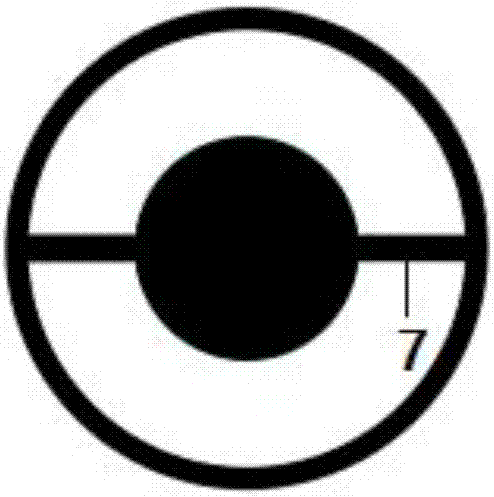
[0030] according to figure 1 As shown, a novel plasma antenna of the present invention includes a discharge chamber 1, a gas cylinder 2, a radio frequency power supply 3, a glass tube 4, and an AC power supply 5; the discharge chamber 1 includes a stainless steel cylinder and a stainless steel cylinder arranged outside the stainless steel cylinder. Outer wall, an annular space is formed between the stainless steel cylinder and the stainless steel outer wall as a plasma generation area; the cavity of the glass tube 4 is used as a plasma working area, and the outer wall of the glass tube 4 is provided with a metal patc...


PUM


Abstract

The invention discloses a novel plasma antenna and a usage method thereof. The novel plasma antenna comprises a discharging room, a gas cylinder, a radio-frequency power supply, a glass tube and an alternating-current power supply. Plasma is caused in the discharging room; the plasma enters the glass tube to work to form a plasma antenna and thus realize signal receiving and transmitting. A plasma generation zone and a plasma working zone are separated and work independently, so that the density of the plasma in the plasma working zone can be adjusted and thus the working frequency range of the plasma antenna can be increased.

Description

technical field [0001] The invention relates to the field of plasma antennas, in particular to a plasma antenna with adjustable plasma density. Background technique [0002] Plasma antenna is an antenna that uses ionized gas as the electromagnetic energy conduction medium. Compared with the traditional antenna that uses metal conductors as the conduction medium, plasma is used as the medium of electromagnetic radiation, and plasma exists as the fourth state of matter, including Ions, electrons, and molecules are electrically neutral as a whole, and have the advantage of flexible design. Their length can be changed with the excitation power. The bandwidth, impedance, directivity, and radiation direction of the plasma antenna can vary with the frequency of the plasma and Due to its high frequency, when it is working, the electromagnetic waves emitted by the enemy radar are absorbed on the one hand, reflected on the other hand and deviate from the original direction, and the an...

Claims


Application Information

Patent Timeline
Patent Type & Authority Applications(China)
IPC IPC(8): H01Q1/26H01Q1/36
CPCH01Q1/26H01Q1/36
Inventor 魏相飞
Owner WEST ANHUI UNIV
Learn More