Virtual synchronous power generation method and system based on inverter

A technology of virtual synchronous power generation and virtual synchronous motor, which is applied in the field of electric power, can solve problems such as difficult synchronization of grid-connected inverters and micro-grids, and achieve the effects of closed-loop control, stable power output, and improved stability

Inactive Publication Date: 2017-07-21
SHENZHEN SINEXCEL ELECTRIC
4 Cites 3 Cited by

AI-Extracted Technical Summary

Problems solved by technology

[0003] The technical problem to be solved by the embodiments of the present invention is to provide an inverter-based virtual synchronous power generation...

Method used

The virtual synchronous power generation method based on the inverter provided by the embodiment of the present invention, by regulating the current at the grid-connected point of the inverter, generates a virtual synchronous generator terminal voltage, and then contro...

Abstract

The embodiment of the invention discloses a virtual synchronous power generation method and system based on an inverter, and the method comprises the steps: detecting a current at a grid connected point; carrying out the regulation and control of the current according to a preset control link, and generating an end voltage of a virtual synchronous power generator; generating a drive signal according to the end voltage of the virtual synchronous power generator, and controlling the on/off of a switching device in the inverter. According to the embodiment of the invention, the method achieves the closed-loop control of a system, can achieve the stable power output, and maintains the synchronization with a microgrid, and facilitates the improvement of the stability of a power grid.

Application Domain

Single network parallel feeding arrangements

Technology Topic

Virtual synchronyVirtual synchronous generator +8

Image

  • Virtual synchronous power generation method and system based on inverter
  • Virtual synchronous power generation method and system based on inverter
  • Virtual synchronous power generation method and system based on inverter

Examples

  • Experimental program(2)

Example

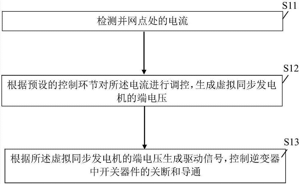
[0048] See figure 1 , is the flow chart of the first embodiment of the inverter-based synchronous power generation method provided by the present invention, and the method includes:
[0049] S11. Detect the current at the grid-connected point. Specifically, the inverter can be incorporated into the microgrid through inductance. Among them, the type of inverter includes but not limited to two-level inverter, three-level inverter and multi-level inverter, and the DC power supply in the inverter circuit includes but not limited to capacitor, super capacitor and battery . In this embodiment, the current at the grid-connected point can be obtained through the current detection device.
[0050]S12. Regulate the current according to a preset control link to generate a terminal voltage of the virtual synchronous generator. Specifically, some droop control strategies can be used to regulate the current at the grid-connected point to simulate the inertia and damping characteristics of the virtual synchronous generator.
[0051] S13. Generate a driving signal according to the terminal voltage of the virtual synchronous generator, and control turning off and turning on of the switching device in the inverter. Specifically, by controlling the off and on of the switching devices in the inverter, the midpoint voltage of the bridge arm of the inverter meets the mechanical and electromagnetic characteristics of the virtual synchronous generator, so that the inverter incorporated into the microgrid can realize virtual Synchronous generator function.
[0052] The inverter-based virtual synchronous power generation method provided by the embodiment of the present invention generates a virtual synchronous generator terminal voltage by regulating the current at the grid-connected point of the inverter, and then controls the switching off and conducting of the switching devices in the inverter. Through control, the closed-loop control of the system is realized, stable power output can be achieved, and synchronization with the microgrid is maintained, which is conducive to improving the stability of the power grid.

Example

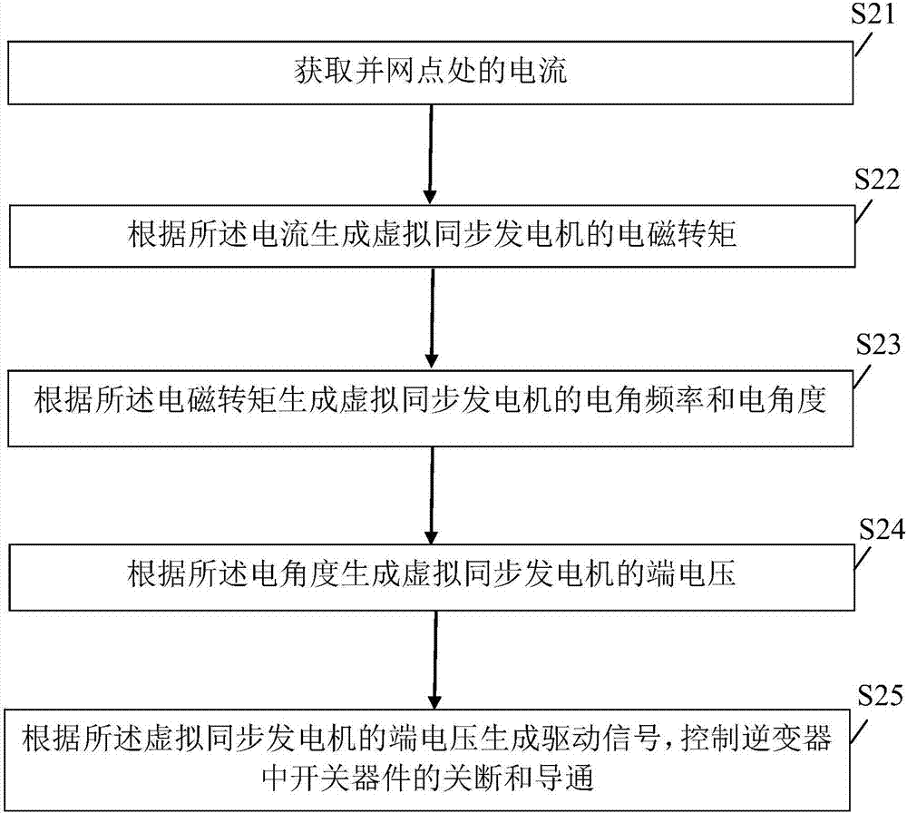
[0053] See figure 2 , is the flow chart of the second embodiment of the inverter-based synchronous power generation method provided by the present invention, the method includes:
[0054] S21. Obtain the current at the grid-connected point.
[0055] S22. Generate the electromagnetic torque of the virtual synchronous generator according to the current. Specifically, a virtual synchronous motor is assumed without a damper winding, and a constant current source is used instead of the field winding circuit. Step S22 may include: the current i at the grid-connected node a i b i c Perform abc-dq phase coordinate conversion to generate i d i q; According to the first formula T e = 1.5pL m i f i q Calculate the electromagnetic torque T of the virtual synchronous generator e , where p is the number of pole pairs of the virtual synchronous motor, L m is the mutual inductance of the virtual synchronous motor, i f is the excitation current. For example, according to L m =L-L Is Calculate the mutual inductance L of the virtual synchronous motor m , where L is the stator inductance, L Is For leakage inductance. Wherein, the abc-dq phase coordinate conversion belongs to the common knowledge in the field, and will not be repeated here.
[0056] S23. Generate the electrical angular frequency and electrical angle of the virtual synchronous generator according to the electromagnetic torque. Specifically, step S23 may include: according to the second formula Calculate the rotor angular frequency ω r , where J is the moment of inertia of the virtual synchronous generator, F is the friction coefficient of the virtual synchronous generator, T m is the load torque; according to the rotor angular frequency ω r Calculate the electrical angular frequency ω of the virtual synchronous motor with the number of pole pairs p of the virtual synchronous motor, for example, ω=p*ω r; Integrate the electrical angular frequency ω of the virtual synchronous motor to generate the electrical angle θ of the virtual synchronous motor.
[0057] S24. Generate a terminal voltage of the virtual synchronous generator according to the electrical angle. Specifically, step S24 may include: according to the third formula Fourth formula e q =ωL m i f Calculate the terminal voltage e of the virtual synchronous generator d and e q; put e d and e q Perform dq-abc phase coordinate conversion to generate e a 、e b and e c. Similarly, the dq-abc phase coordinate conversion belongs to common knowledge in the field, and will not be repeated here.
[0058] S25. Generate a driving signal according to the terminal voltage of the virtual synchronous generator, and control turning off and turning on of the switching device in the inverter.
[0059] The inverter-based virtual power generation method provided by the preferred embodiment of the present invention introduces the voltage and frequency difference adjustment characteristics similar to the synchronous generator into the power outer loop of the grid-connected inverter, and provides some grid-connected inverter The droop control strategy of the inverter controls the grid-connected inverter by referring to the mechanical equation and electromagnetic equation of the synchronous generator, so that the grid-connected inverter can be comparable to the synchronous generator in terms of mechanism and external characteristics.
[0060] See image 3 , is a schematic structural diagram of the first embodiment of the inverter-based synchronous power generation system provided by the present invention, the system includes:
[0061] The inverter 310 is integrated into the microgrid through inductance. Types of inverters include but not limited to two-level inverters, three-level inverters and multi-level inverters, and DC power sources in inverter circuits include but not limited to capacitors, super capacitors and batteries.
[0062] The current detection module 320 is used to detect the current at the grid connection point.
[0063] The control module 330 is configured to regulate the current according to a preset control link to generate a terminal voltage of the virtual synchronous generator. Specifically, some droop control strategies can be used to regulate the current at the grid-connected point to simulate the inertia and damping characteristics of the virtual synchronous generator.
[0064] The driving module 340 is configured to generate a driving signal according to the terminal voltage of the virtual synchronous generator, and control turning off and turning on of the switching device in the inverter. Specifically, the driving module 340 controls the switching devices in the inverter to be turned off and on, so that the midpoint voltage of the bridge arm of the inverter meets the mechanical and electromagnetic characteristics of the virtual synchronous generator, so that the inverter integrated into the microgrid can The generator realizes the function of virtual synchronous generator.
[0065] The inverter-based virtual synchronous power generation system provided by the embodiment of the present invention generates a virtual synchronous generator terminal voltage by regulating the current at the grid-connected point of the inverter, and then controls the switching off and conducting of the switching devices in the inverter. Through control, the closed-loop control of the system is realized, stable power output can be achieved, and synchronization with the microgrid is maintained, which is conducive to improving the stability of the power grid.
[0066] See Figure 4 , is a schematic structural diagram of the second embodiment of the inverter-based synchronous power generation system provided by the present invention. Wherein, the control module 330 includes:
[0067] The electromagnetic torque algorithm module 331 is configured to generate the electromagnetic torque of the virtual synchronous generator according to the current. Specifically, a virtual synchronous motor is assumed without a damper winding, and a constant current source is used instead of the field winding circuit. The electromagnetic torque algorithm module 331 may include: a current coordinate conversion module for converting the current i at the grid-connected node a i b i c Perform abc-dq phase coordinate conversion to generate i d i q; The electromagnetic torque calculation module is used for according to the first formula T e = 1.5pL m i f i q Calculate the electromagnetic torque T of the virtual synchronous generator e , where p is the number of pole pairs of the virtual synchronous motor, L m is the mutual inductance of the virtual synchronous motor, i f is the excitation current. For example, according to L m =L-L Is Calculate the mutual inductance L of the virtual synchronous motor m , where L is the stator inductance, L Is For leakage inductance.
[0068] The electrical angular frequency algorithm module 332 is configured to generate the electrical angular frequency and electrical angle of the virtual synchronous generator according to the electromagnetic torque. Specifically, the electrical angular frequency algorithm module 332 may include: a rotor angular frequency calculation module, configured to Calculate the rotor angular frequency ω r , where J is the moment of inertia of the virtual synchronous generator, F is the friction coefficient of the virtual synchronous generator, T m is the load torque; the electrical angular frequency calculation module is used to calculate the angular frequency ω according to the rotor r Calculate the electrical angular frequency ω of the virtual synchronous motor with the number of pole pairs p of the virtual synchronous motor, for example, ω=p*ω r; An electrical angle calculation module, configured to integrate the electrical angular frequency ω of the virtual synchronous motor to generate an electrical angle θ of the virtual synchronous motor.
[0069] A terminal voltage algorithm module 333, configured to generate the terminal voltage of the virtual synchronous generator according to the electrical angle. Specifically, the terminal voltage algorithm module 333 may include: a terminal voltage calculation module, configured to Fourth formula e q =ωL m i f Calculate the terminal voltage e of the virtual synchronous generator d and e q; Voltage coordinate conversion module, used to transform e d and e q Perform dq-abc phase coordinate conversion to generate e a 、e b and e c.
[0070] The inverter-based virtual power generation system provided by the preferred embodiment of the present invention introduces the voltage and frequency difference adjustment characteristics similar to synchronous generators in the power outer loop of the grid-connected inverter, and provides some grid-connected inverters The droop control strategy of the inverter controls the grid-connected inverter by referring to the mechanical equation and electromagnetic equation of the synchronous generator, so that the grid-connected inverter can be comparable to the synchronous generator in terms of mechanism and external characteristics.
[0071] Figure 5 It is a schematic diagram of the control link provided by a preferred embodiment of the present invention. like Figure 5 As shown, the rotation angle of the dq coordinate system is θ, and the detected current i is first passed through the first coordinate converter a i b i c convert to i d i q , then i q and 1.5pL m i f i q respectively input into the first multiplier to obtain the electromagnetic torque T e. The electromagnetic torque T e , load torque T m Negative number of Fω r Negative numbers of are input to the first adder respectively, to get Will Enter the 1/J divider to get followed by Input into the first integrator, we can get ω r , ω output by the first integrator r After being multiplied by F multiplier and F, Fω is obtained r , take the negative number as an input of the first adder. At the same time, the output ω of the first integrator r After passing through the p multiplier, ω is obtained. ω and L m i f respectively input into the second multiplier to get e q; At the same time, L m i f Input to the first differentiator, generating e d. In addition, ω is also input into the second integrator to generate θ, and θ output by the second integrator is simultaneously input into the first coordinate converter and the second coordinate converter. The second coordinate converter converts the e output from the first differentiator according to the θ output from the second integratord and the e of the second multiplier output q convert to e a 、e b and e c. Finally, the PWM generator outputs e according to the second coordinate converter a 、e b and e c Generate drive signals to control the switching off and on of switching devices in the inverter.
[0072] Those of ordinary skill in the art can understand that all or part of the processes in the methods of the above embodiments can be implemented through computer programs to instruct related hardware, and the programs can be stored in a computer-readable storage medium. During execution, it may include the processes of the embodiments of the above-mentioned methods. Wherein, the storage medium may be a magnetic disk, an optical disk, a read-only memory (Read-Only Memory, ROM) or a random access memory (Random Access Memory, RAM) and the like.

PUM

no PUM

Description & Claims & Application Information

We can also present the details of the Description, Claims and Application information to help users get a comprehensive understanding of the technical details of the patent, such as background art, summary of invention, brief description of drawings, description of embodiments, and other original content. On the other hand, users can also determine the specific scope of protection of the technology through the list of claims; as well as understand the changes in the life cycle of the technology with the presentation of the patent timeline. Login to view more.

Similar technology patents

Power supply line current signal wireless acquisition three-phase synchronous circuit

PendingCN112213559AStable power output
Owner:河南普惠电力科技有限公司

Unstable-electric energy comprehensive treatment system

InactiveCN110410163AStable power output
Owner:黄琳

Bearing performance detection device

ActiveCN112268499Aeasy to observeStable power output
Owner:DELMAR BEARING CO LTD

Ocean energy collection device

InactiveUS20220178341A1stable power outputsimple structure
Owner:SHANGHAI UNIV

Copper head pulling-out device for coal mine

InactiveCN108972454AStable power outputReduce labor intensity
Owner:高永强
Why Eureka
Try Eureka