
Uniform flowing liquid glue bottle

A glue bottle, liquid technology, applied in the direction of closure, packaging, transportation and packaging, etc., can solve the problems of waste, difficulty of liquid glue, excessive glue application, etc.

Inactive Publication Date: 2017-07-25
朱素央
View PDF0 Cites 4 Cited by
  • Summary
  • Abstract
  • Description
  • Claims
  • Application Information

AI Technical Summary

Problems solved by technology

[0002] As we all know, glue can be divided into solid glue and liquid glue according to the state of use. Especially for liquid glue, because it exists in a liquid state, the manufacturer has to fill the liquid glue into the bottle and package it when it leaves the factory. However, In the user's actual use process, there are often the following two defects: 1. Since the glue bottle in the prior art is all directly provided with a glue cover at the bottleneck position of the bottle body, when the user turns over the glue bottle to use glue, the glue bottle Under the action of gravity, the glue in the bottle is directly drained out through the drainage hole opened on the glue cover. At this time, because all the glue in the bottle is under the action of gravity, the flow rate of glue is very fast, which often leads to excessive glue application by users. And uneven flow out, serious waste; 2. Due to the frequent use of glue by the user, the sealing performance between the bottle body and the bottle cap of the glue bottle is missing or the user forgets to cover the bottle cap, so that the liquid glue in the bottle directly Contact with the external environment (such as air, temperature, humidity and other environmental factors), and make the liquid glue hard to continue to use

Method used


Image

  • Uniform flowing liquid glue bottle
  • Uniform flowing liquid glue bottle
  • Uniform flowing liquid glue bottle

Examples


Embodiment Construction

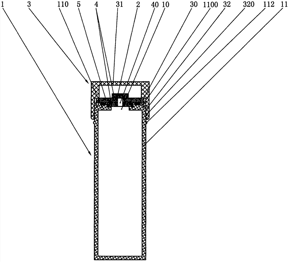
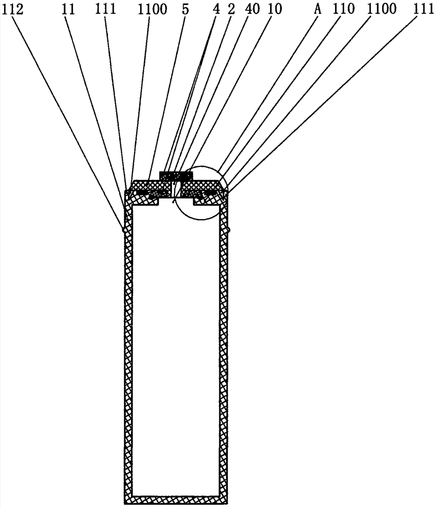
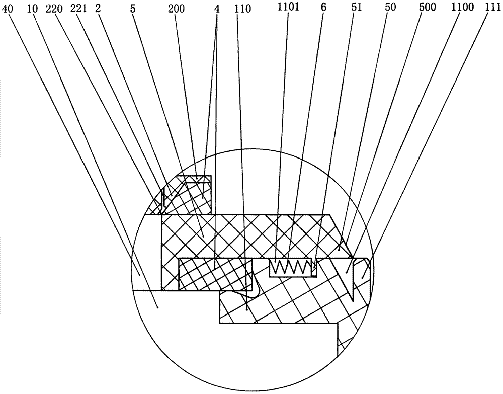
[0018] Such as Figure 1-7 Shown, the specific embodiment of the present invention is a kind of even flow type liquid glue bottle, figure 1 combine figure 2 and image 3 Show, the liquid glue bottle of present embodiment comprises bottle body 1, glue cap 2 and bottle cap 3, and the top position of described bottle body 1 forms the bottleneck 10 that is open state, and described glue cap 2 is arranged on described bottleneck 10 above, the glue cover 2 has a rounded platform structure with a wide top and a narrow bottom, and is combined with Figure 7 It is more obvious that the glue cover 2 has an upper circular table top 20, a lower circular table top 21 and a side cone surface 22, further combining Figure 5 It can be seen that the position of the bottle mouth 10 has a rounded table cavity 400 adapted to the rounded table type glue cover 2, and the side cone surface 22 of the glue cover 2 is provided with several , a diversion groove 220 extending along the slope directi...


PUM


Abstract

The invention relates to a flow-balanced liquid glue bottle, which comprises a bottle body, a glue cap and a bottle cap. The top of the bottle body forms an open bottle mouth, and the glue cap is arranged above the bottle mouth. The glue cover has a rounded table structure with a wide top and a narrow bottom, and has an upper round table top, a lower round table top and a side cone surface. The position of the bottle mouth has a rounded table cavity that is adapted to the rounded table type glue cover. The side cone surface of the glue cover is provided with several diversion grooves starting from the edge of the lower circular table surface and extending along the slope direction of the side cone surface. Drain holes in the round top. The liquid glue bottle of the present invention is not only simple in structure, but also has diversion grooves and drainage holes that are not in line with the glue flow channel, so that the application of glue is more uniform and economical, effectively improving the use efficiency of liquid glue, and the present invention The liquid glue bottle has good sealing performance and long service life.

Description

technical field [0001] The invention relates to the field of stationery and sports articles, in particular to a liquid glue bottle. Background technique [0002] As we all know, glue can be divided into solid glue and liquid glue according to the state of use. Especially for liquid glue, because it exists in a liquid state, the manufacturer has to fill the liquid glue into the bottle and package it when it leaves the factory. However, In the user's actual use process, there are often the following two defects: 1. Since the glue bottle in the prior art is all directly provided with a glue cover at the bottleneck position of the bottle body, when the user turns over the glue bottle to use glue, the glue bottle Under the action of gravity, the glue in the bottle is directly drained out through the drainage hole opened on the glue cover. At this time, because all the glue in the bottle is under the action of gravity, the flow rate of glue is very fast, which often leads to exces...

Claims


Application Information

Patent Timeline
IPC IPC(8): B65D47/06
CPCB65D47/06
Inventor 朱素央
Owner 朱素央
Learn More