Capping device

A cover cover and conveying path technology, which is applied in the field of capping devices, can solve problems such as hidden dangers in the operation of capping devices, short cap conveying paths, and weak anti-risk capabilities, and achieve structural optimization, safety and convenience of cap conveying paths The effect of improving and improving safety

Active Publication Date: 2017-07-25
HANGZHOU ZHONGYA MACHINERY CO LTD
View PDF8 Cites 6 Cited by
  • Summary
  • Abstract
  • Description
  • Claims
  • Application Information

AI Technical Summary

Problems solved by technology

[0004]The existing capping device is close to the capping station and the cap conveying path is extremely short, so the capping device has potential safety hazards and anti-risk capabilities Very weak and inconvenient to operate

Method used


Image

  • Capping device
  • Capping device
  • Capping device

Examples


Embodiment Construction

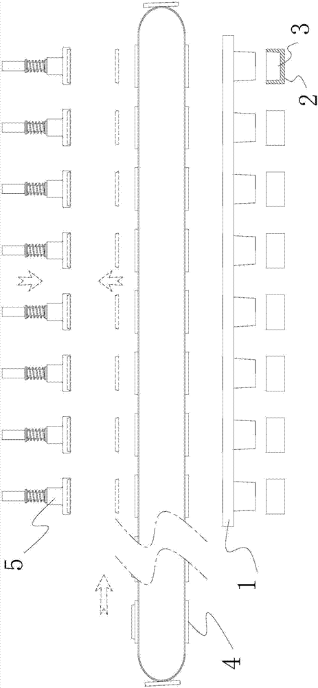
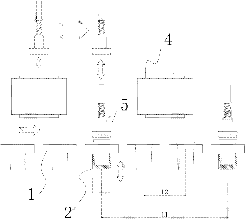
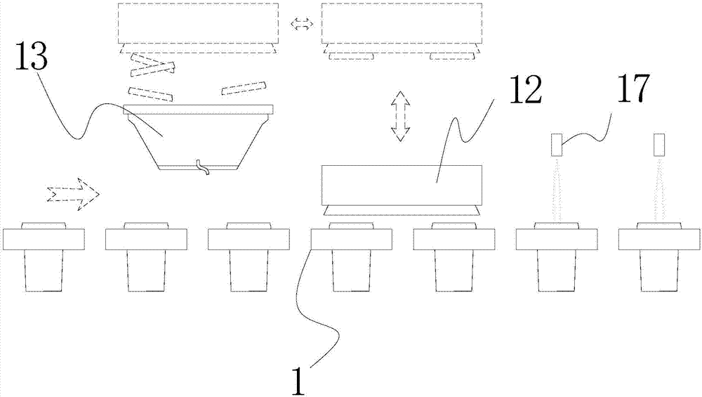
[0026] The capping device includes a frame, a cup conveying component, a handling component, a cap conveying component, a capping supporting component, and a rejecting component.

[0027] The cup conveying assembly includes a chain, a template 1, a gear, and a motor. The gear is installed on the frame through the rotating shaft, and the gear can rotate. Two gears are installed on one rotating shaft, and four gears are installed on the frame. The motor is installed on the frame and connected with the gear, and the motor can drive the gear to rotate. The cup conveying assembly is provided with two chains, and each chain is installed on the gears on the two rotating shafts on the same side, and the chains are driven to move when the gears rotate. The template 1 is a flat cuboid structure as a whole, and there are eight through-hole structures arranged equidistantly on the template 1. These through-holes are arranged in the same straight line direction, and these through-holes ar...


PUM


Abstract

The invention discloses a capping device. In the capping device, a cap conveying path is arranged in the direction perpendicular to a cup conveying path, and the length of the cap conveying path is increased in the direction. Functional differentiation of the cap conveying path is achieved. A cap supplying station is externally arranged. Circulation operation is conducted on the cap conveying path. By the adoption of the capping device, the cap conveying path structure is optimized, the capping operation area is arranged on the side of the cup conveying path, so that the capping operation height is reduced, and the safety, stability and convenience of the operation of the whole machine are greatly improved.

Description

technical field [0001] The invention relates to a capping device. Background technique [0002] Among dairy products that use cups as containers, products with larger volumes are produced in the form of single cups. Such cups are usually topped with a lid to provide structural support in terms of product appearance, spoon storage, and user convenience. Therefore, the product production process must go through the capping link, that is, the independent lid and the independent cup are combined according to the predetermined connection relationship. This step has realized automatic mechanical operation in the field of industrial production. However, due to the defects of the capping technology, there are obvious technical problems in the capping device in the prior art. The reason is that in the existing capping device, the cap supplying station and the capping station are close together in spatial layout, especially the structure that the cap supplying station is next to the...

Claims


Application Information

Patent Timeline
Patent Type & Authority Applications(China)
IPC IPC(8): B67B3/00B65G15/58B65G47/90B65B57/02
CPCB65B57/02B65G15/58B65G47/901B67B3/00
Inventor 史中伟史正王炜夏杰
Owner HANGZHOU ZHONGYA MACHINERY CO LTD
Why Eureka
Try Eureka