Sectional warp beam and creel of assembling device

A technology of section warping and creel, which is applied in the direction of creel, warping machine, transportation and packaging, etc. It can solve the problems of unusable yarn, relative force and time consumption, etc.

Active Publication Date: 2017-07-25
KARL MAYER ROTAL SRL
View PDF5 Cites 1 Cited by
  • Summary
  • Abstract
  • Description
  • Claims
  • Application Information

AI Technical Summary

Problems solved by technology

This means that a certain length of yarn per section warp beam cannot be used
[0005] In addition, the preparation is relatively labor- and time-consuming

Method used


Image

  • Sectional warp beam and creel of assembling device
  • Sectional warp beam and creel of assembling device
  • Sectional warp beam and creel of assembling device

Examples


Embodiment Construction

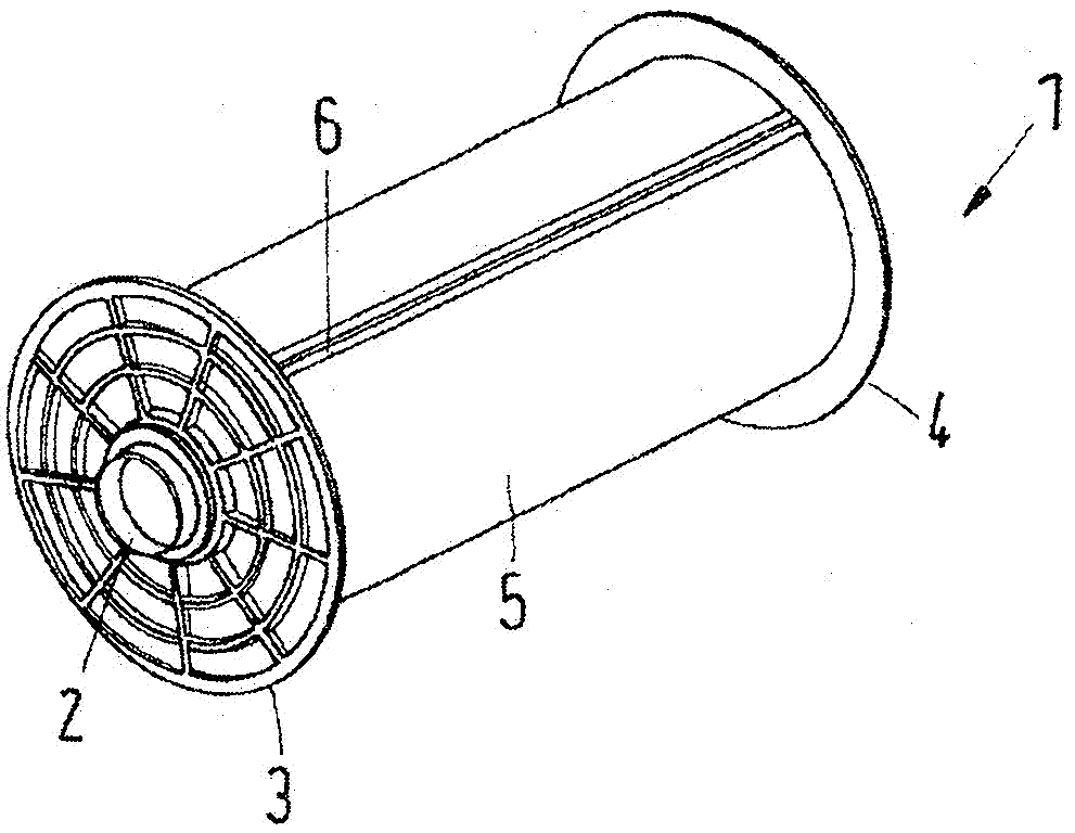
[0030] figure 1 A section warp beam 1 is shown with a core 2 and two side disks 3 , 4 at both ends of said core 2 . A yarn sheet 5 is wound on said core 2 . The yarn sheets consist of a plurality of yarns arranged side by side in the longitudinal direction of the core 2 and running in parallel.

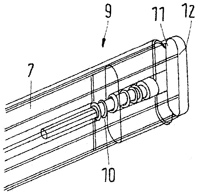
[0031] Clamps 6 extend parallel to said core 2 . The clamp 6 (which is in figure 2 shown in more detail in ) holds the yarns side by side along the width direction of the section warp beam 1 at the ends and acts equally on all yarns. To this end, the tongs 6 have a tong core 7 and a clip 8 . The yarns of the yarn sheet 5 are guided in a U-shape around the clamping core 7 and are then fixed on the clamping core 7 with the clamps 8 . This fixing is enough to reliably fix and maintain the yarn of the yarn sheet 5 at the clamp 6 .

[0032] if possible in figure 1 As can be seen in , the clamp 6 is fixed between the side disks 3, 4 of the section beam. For this use in image 3 Th...


PUM


Abstract

The invention relates to a sectional warp beam and a creel of an assembling device. Specifically, the sectional warp beam (1) is provided with a core (2) and two side disks (3, 4) at both end portions of the core (2). The sectional warp beam facilitates the preparation of thread pieces for assembling. For this purpose, the sectional warp beam (1) has a clip (6) and a fastening device by means of which the clip (6) can be secured between the side disks (3, 4).

Description

technical field [0001] The invention relates to a section warp beam with a core, two side disks at the two ends of the core and clamps (Kluppe). [0002] The invention furthermore relates to a creel of a doubling device with at least one warp beam support for accommodating such a section warp beam and a creel output. Background technique [0003] In a doubling device, the yarn sheets, which are drawn from at least two, but usually more, section warp beams, are united into one warp beam. During the combining process it is also possible to also process the yarn sheet, for example to provide it with a size application. [0004] In order to be able to unite the yarn sheets, the section warp beams must be arranged in a creel which is arranged upstream of the input of the paralleling device. In order to prepare for the doubling process, the yarn sheet must then be drawn from each section warp beam and drawn to the input of the doubling device. Usually this is done in such a way...

Claims


Application Information

Patent Timeline
Patent Type & Authority Applications(China)
IPC IPC(8): D02H1/00D02H3/00
CPCD02H1/00D02H3/00D02H13/30D02H13/36D02H13/38B65H65/005B65H75/14B65H2404/36B65H2701/31
Inventor E.保利
Owner KARL MAYER ROTAL SRL
Why Eureka
Try Eureka