Incinerator dynamic turbulent flow rotational flow device and working method thereof

A swirling device and incinerator technology, which is applied in the direction of combustion method, incinerator, combustion type, etc., can solve the problems that the emission cannot be continuously and stably met, the garbage cannot be completely burned, and the oxygen supply is insufficient, and the structure is simple, the design is reasonable, The effect of curbing emissions

Active Publication Date: 2017-07-25
广东纳翕燚资源综合利用科技有限公司
View PDF6 Cites 0 Cited by
  • Summary
  • Abstract
  • Description
  • Claims
  • Application Information

AI Technical Summary

Problems solved by technology

[0002] The furnace body rotating device of the rotary garbage incinerator is installed on the support frame and rotates under the drive of the driving device. The top of the furnace body has a flue gas pipe, and the oxygen supply method is supplied by wind from one end, and the oxygen is supplied in one direction in the axial direction. The method is prone to insufficient oxygen supply, the garbage cannot be completely burned, and primary pollutants (mainly dioxins and heavy metal pollutants) are produced, and the discharge cannot be continuously and stably up to the standard, especially at the bottom of the furnace. Due to the accumulation of garbage, the garbage at the bottom of the furnace is difficult to achieve complete combustion

Method used


Image

  • Incinerator dynamic turbulent flow rotational flow device and working method thereof
  • Incinerator dynamic turbulent flow rotational flow device and working method thereof

Examples


Embodiment Construction

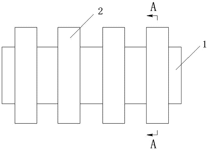
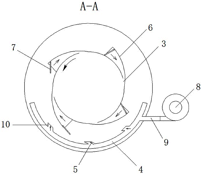
[0014] Such as Figure 1~2 As shown, a dynamic turbulent swirling device for an incinerator includes a self-rotating incinerator 1, and a plurality of annular shells 2 arranged in the axial direction are set on the periphery of the incinerator, and the incinerator furnace where the annular shell 2 is located A plurality of air inlets 3 are arranged at intervals around the body, and an arc-shaped air distribution pipe 4 located below the incinerator 1 is arranged inside the annular casing 2. A plurality of air outlets 5 are arranged at intervals on the upper side of the air distribution pipe 4. Inside the annular casing Each air inlet 3 is provided with a horn-shaped air inlet guide shell 6, the small end of the air inlet guide shell 6 is connected to the air inlet 3, and the air inlet direction of the air inlet guide shell 6 is opposite to the rotation direction of the incinerator 1. The air distribution pipe blows air into the annular shell 2 and blows oxygen into the inciner...


PUM


Abstract

The invention relates to an incinerator dynamic turbulent flow rotational flow device and a working method thereof. The incinerator dynamic turbulent flow rotational flow device comprises a self-rotating incinerator, wherein a plurality of annular shells are arranged on the periphery of the incinerator in the axial direction in a sleeving manner; a plurality of air inlets are formed in the circumferential part of the incinerator body at intervals, and the annular shells are positioned at the circumferential part of the incinerator body; arc-shaped air distribution pipes positioned below the incinerator are arranged in the annular shells; a plurality of air inlets are formed in the upper sides of the air distribution pipes at intervals; an ox horn shaped air inlet guide shell is arranged at each air inlet in each annular shell; the smaller ends of the air inlet guide shells are in butt joint with the air inlets; and the air inlet direction of the air inlet guide shells is opposite to the rotating direction of the incinerator. The incinerator dynamic turbulent flow rotational flow device is simple in structure and reasonable in design; the air is blown in the hearth of the incinerator through the air inlets in the circumferential part of the incinerator body to feed oxygen turbulence, so that sufficient oxygen supply and complete mixing are ensured; and in addition, the wind blown into the incinerator can form a rotational flow, so that the air can be uniformly distributed, uniform and sufficient combustion can be ensured, and emission of primary pollutant is chocked.

Description

technical field [0001] The invention relates to a dynamic turbulent swirling device for an incinerator and a working method thereof. Background technique [0002] The furnace body rotating device of the rotary garbage incinerator is installed on the support frame and rotates under the drive of the driving device. The top of the furnace body has a flue gas pipe, and the oxygen supply method is supplied by wind from one end, and the oxygen is supplied in one direction in the axial direction. The method is prone to insufficient oxygen supply, the garbage cannot be completely burned, and primary pollutants (mainly dioxins and heavy metal pollutants) are produced, and the discharge cannot be continuously and stably up to the standard, especially at the bottom of the furnace. Due to the accumulation of garbage, the garbage at the bottom of the furnace is difficult to achieve complete combustion. Contents of the invention [0003] In view of this, the object of the present inven...

Claims


Application Information

Patent Timeline
Patent Type & Authority Applications(China)
IPC IPC(8): F23G5/20F23G5/32F23G5/44
CPCF23G5/20F23G5/32F23G5/44F23G2207/30F23G2203/207Y02E20/34
Inventor 吴谦信吴煜恒黄振康黄泽春陈志杨
Owner 广东纳翕燚资源综合利用科技有限公司
Why Eureka
Try Eureka