Handheld cooling fan

A cooling fan and hand-held technology, applied in the field of hand-held cooling fans, can solve problems such as poor cooling effect, achieve the effects of ensuring gas circulation channels, simple device structure, convenience and practical cost

Inactive Publication Date: 2017-07-25
XINYANG NORMAL UNIVERSITY
View PDF5 Cites 0 Cited by
  • Summary
  • Abstract
  • Description
  • Claims
  • Application Information

AI Technical Summary

Problems solved by technology

[0003] The purpose of the present invention is to provide a hand-held cooling fan to solve the problem of poor cooling effect of existing hand-held fans

Method used


Image

  • Handheld cooling fan
  • Handheld cooling fan
  • Handheld cooling fan

Examples


Embodiment 2

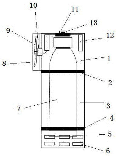
[0037] Embodiment 2 of the hand-held cooling fan of the present invention: the difference from Embodiment 1 is that the middle and lower parts of the cold body placement cavity are integrated, and only the middle and upper parts can be separated.

Embodiment 3

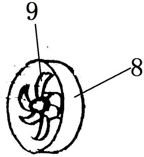
[0038] Embodiment 3 of the hand-held cooling fan of the present invention: the difference from Embodiment 1 is that there is no shield for protecting the fan blades on the side wall of the upper part of the cavity where the cooling body is placed.

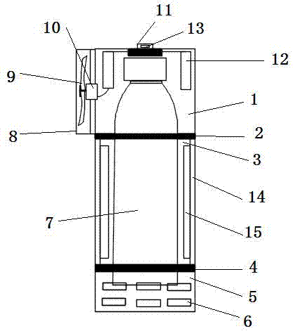
[0039] Embodiment four of the hand-held cooling fan of the present invention: as Figure 5 As shown, the difference from Embodiment 1 is that the inner wall of the heat insulating layer 14 is elliptical, the inner side of the inner wall is not provided with fins, and the two ends of the ellipse serve as passages for air flow.

[0040] Embodiment five of the hand-held cooling fan of the present invention: as Image 6As shown, the difference from Embodiment 1 is that the inner wall of the heat insulating layer 14 is circular, and four channels for air flow are provided on the circular inner wall.

[0041] Embodiment six of the hand-held cooling fan of the present invention: as Figure 7 As shown, the difference from Embodiment 1 is...


PUM


Abstract

The invention relates to a handheld cooling fan which comprises a fan device and a cooling body storage cavity. An air intake hole is formed in the side wall of the cooling body storage cavity. A channel for air circulation is formed between the air intake hole and an air outlet of the fan device. When the fan device operates, hot air can be sucked into the cooling body storage cavity from the outside of the cooling body storage cavity through negative pressure firstly, then the hot air is cooled through a bottle, filled with a cooling medium, in the cooling body storage cavity, and finally, cold air is blown from fan blade positions. The handheld cooling fan is simple in structure, convenient to use, practical, low in cost and easy to apply and popularize.

Description

technical field [0001] The invention relates to a fan device, in particular to a hand-held cooling fan. Background technique [0002] When people go out to play or exercise in summer, they will sweat profusely because of the hot weather. At this time, tools for cooling are needed, and there are no air conditioners and electric fans outdoors for cooling. In view of this problem, there is currently a hand-held fan, including fan blades, electric motors, batteries and handles, wherein the fan blades, electric motors and batteries form a fan device, and the fan device drives the electric motor through the battery to rotate the fan blades. Generate wind. Although this fan can produce wind, it cannot blow out icy wind, and the cooling effect is relatively poor. Contents of the invention [0003] The purpose of the present invention is to provide a hand-held cooling fan to solve the problem of poor cooling effect of the existing hand-held fans. [0004] In order to achieve the...

Claims


Application Information

Patent Timeline
Patent Type & Authority Applications(China)
IPC IPC(8): F24F5/00F04D25/08
CPCF04D25/08F24F5/0017F24F5/0096F24F2221/18Y02E60/14
Inventor 赵志杰严丹
Owner XINYANG NORMAL UNIVERSITY
Why Eureka
Try Eureka