Measuring method for limiting shearing stress of nanometer material

A technology of shear stress and nano-materials, applied in the direction of applying stable shear force to test the strength of materials, etc., can solve the problem of low precision, achieve the effect of high quantitative measurement precision, low requirements, and ensure reliability

Inactive Publication Date: 2017-07-25
XIANGTAN UNIV
View PDF1 Cites 8 Cited by
  • Summary
  • Abstract
  • Description
  • Claims
  • Application Information

AI Technical Summary

Problems solved by technology

In particular, this method overcomes the shortcomings of the traditional ultimate shear stress measurement method that cannot be quantitatively measured, has low precision, and is not suitable for nanomaterials. precision and convenience

Method used


Image

  • Measuring method for limiting shearing stress of nanometer material
  • Measuring method for limiting shearing stress of nanometer material
  • Measuring method for limiting shearing stress of nanometer material

Examples


Embodiment 1

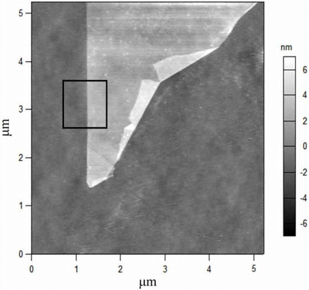
[0049] The AFM model used in Example 1 is: Cypher ES, Asylum Research, CA; the probe model used for friction measurement is: AC240TS, Olympus, with a radius of about 9nm, an elastic modulus of 190GPa, and a friction calibration coefficient of 566.33nN / V; the sample to be tested is graphene prepared by mechanical exfoliation method, and the elastic modulus is 1000GPa. figure 2 is the AFM surface topography image of the graphene. The entire nanomaterial ultimate shear stress measurement experiment process is completed in a clean room with a temperature of 23°C and a humidity of 50%.

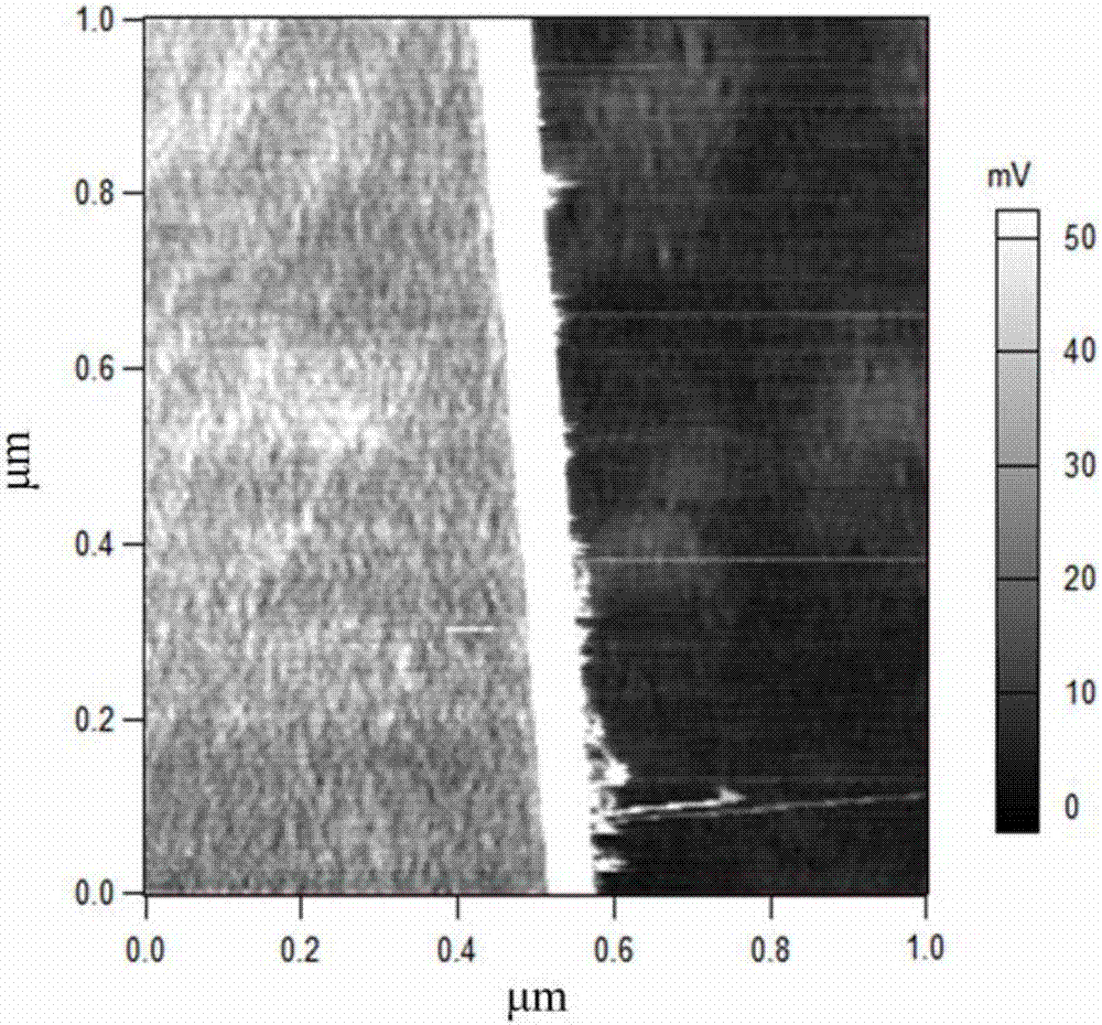
[0050] According to step S11, using the lateral force module of the AFM to measure figure 2 The area where the middle black box is located is in F n = Triboelectric signal under load of 99.31nN, the triboelectric signal image scanned by it is as follows image 3 As shown, the left half of the figure is the friction image of the silicon substrate, and the right half of the area is the friction ...

Embodiment 2

[0054] The AFM model used in Example 2 is: Cypher ES, Asylum Research, CA; the probe model used for friction measurement is: AC240TS, Olympus, with a radius of about 9nm, an elastic modulus of 190GPa, and a friction calibration coefficient of 566.33nN / V; the sample to be tested is MoS 2 Nanosheets with an elastic modulus of 270GPa. Figure 5 for the MoS 2 AFM surface topography images of nanosheets. The entire nanomaterial ultimate shear stress measurement experiment process is completed in a clean room with a temperature of 23°C and a humidity of 50%.

[0055] According to step S11, using the lateral force module of the AFM to measure Figure 5 The triboelectric signal of the area where the middle black box is located under a load of 9.93nN, the scanned triboelectric signal image is as follows Figure 6 As shown, the upper left triangular area in the figure is the friction image of the silicon substrate, and the lower right triangular area is the MoS 2 Tribological image...


PUM

PropertyMeasurementUnit
radiusaaaaaaaaaa
elastic modulusaaaaaaaaaa

Abstract

The invention relates to a measuring method for a limiting shearing stress of a nanometer material. The method comprises the following steps: by using an atomic force microscope (AFM), applying a normal load Fn and measuring a friction force Ff and an average adhesive force Fad of each point in a selected area on the surface of a sample; calculating the limiting shearing stress of the material according to a formula based on an elastic contact theory and an interface friction theory; processing the limiting shearing stress at each point on the surface of the nanometer material into a distributed image. According to the invention, an atomic force microscope technique based on high mechanical sensitivity, compared with the traditional measuring technique for the limiting shearing stress, has the advantages of higher quantitative measurement precision, low demand on surface appearance of the sample and suitability for various nanometer materials. The widely accepted JKR elastic contact theory and interface friction theory are considered as the theories on which the method provided by the invention is based, the theories are widely applied to the research on the mechanical performances of the nanometer material and the reliability of the measuring method is guaranteed by the theories.

Description

technical field [0001] The invention discloses a method for measuring the limit shear stress of nanomaterials, more specifically, a method based on Bowdon interface friction theory and Johnson-Kendall-Roberts (JKR) adhesive contact theory, using an atomic force microscope (AFM) to measure the surface limit of nanomaterials The method of shear stress belongs to the intersection field of nanotechnology and nanotribology. Background technique [0002] The surface and interface states of nanomaterials have a significant impact on the mechanical properties of materials, and the determination of the ultimate shear stress is of great significance to the reliability and safety design of micro / nano electromechanical systems. Traditional ultimate shear stress measurement methods, such as the three-point bending method (Journal of Materials Science, 1980, 15(12): 3122-3128), can only make qualitative comparisons of ultimate shear stress, and cannot obtain quantitative information. Mono...

Claims


Application Information

Patent Timeline
Patent Type & Authority Applications(China)
IPC IPC(8): G01N3/24
CPCG01N3/24
Inventor 郑学军严鑫洋彭金峰李升峰何文远
Owner XIANGTAN UNIV
Why Eureka
Try Eureka