Full-band rhomboic spring antenna used for mobile phone

A spring antenna, full-band technology, applied in the direction of antenna support/installation device, radiation element structure, etc., can solve the problems of low signal strength and short receiving distance, so as to achieve good signal reception and wide receiving range of the antenna , Strong anti-interference effect

Active Publication Date: 2017-07-25
深圳市拓频物联技术有限公司
View PDF8 Cites 0 Cited by
  • Summary
  • Abstract
  • Description
  • Claims
  • Application Information

AI Technical Summary

Problems solved by technology

[0002] The radio frequency signal output by the radio transmitter is sent to the antenna of the mobile phone through the feeder, and is radiated by the antenna in the form of electromagnetic waves. After the electromagnetic wave reaches the receiving location, it is followed by the antenna and passes through the feeder to the radio receiver. It is especially visible that the antenna is a device for transmitting and receiving electromagnetic waves. Important radio equipment, there is no radio communication without an antenna. At present, as the existing mobile wireless communication technology has higher and higher requirements for transmission rate and anti-interference, various antennas have appeared on the market, and These mobile phone antennas also have the following defects: the receiving distance is relatively short, and the received signal strength is not very high

Method used


Image

  • Full-band rhomboic spring antenna used for mobile phone
  • Full-band rhomboic spring antenna used for mobile phone
  • Full-band rhomboic spring antenna used for mobile phone

Examples


Embodiment Construction

[0018] The preferred embodiments of the present invention will be described below in conjunction with the accompanying drawings. It should be understood that the preferred embodiments described here are only used to illustrate and explain the present invention, and are not intended to limit the present invention.

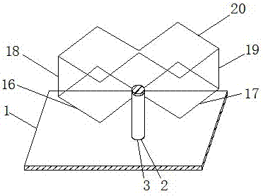
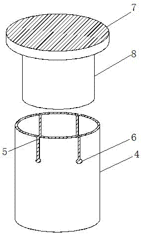
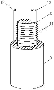
[0019] see Figure 1-4 , the present invention provides a technical solution: a full-band rhombic spring antenna for mobile phones, including a fixed plate 1, a mounting hole 2, a fixing glue 3, a mounting cylinder 4, a placement groove 5, a mounting hole 6, a cap 7, a limit Cylinder 8, cable 9, support platform 10, spring 11, wire connection column 12, core wire column 13, network wire hole 14, core wire hole 15, first diamond-shaped copper wire 16, second diamond-shaped copper wire 17 , the first support copper column 18, the second support copper column 19 and the auxiliary rhombic copper wire 20, the middle part of the fixed plate 1 is provided with a mounting h...


PUM


Abstract

Disclosed is a full-band rhomboic spring antenna used for a mobile phone. The full-band rhomboic spring antenna comprises a first rhomboic copper wire, a second rhomboic copper wire and an auxiliary rhomboic copper wire, wherein a placement groove is formed in the top end of a mounting cylinder; a mounting hole is formed in one end of the placement groove; a cable is arranged at the bottom of a supporting platform; a cable connecting column is arranged on one side of a spring; a cable connecting hole is formed in the outer surface of the top of the cable connecting column; a core wire connecting hole is formed in the outer surface of the top of a core wire connecting column; a first supporting copper column is arranged on one side of the first rhomboic copper wire; the second rhomboic copper wire is arranged at the other end of the core wire connecting hole; a second supporting copper column is arranged on one side of the second rhomboic copper wire; and the auxiliary rhomboic copper wire is arranged at one end of the second supporting copper column. The full-band rhomboic spring antenna has a simple structure, high anti-interference performance, a wide receiving range and high antenna signal receiving and transmitting properties.

Description

technical field [0001] The invention relates to the technical field of mobile phone antennas, in particular to a full-band rhombic spring antenna for mobile phones. Background technique [0002] The radio frequency signal output by the radio transmitter is sent to the antenna of the mobile phone through the feeder, and is radiated by the antenna in the form of electromagnetic waves. After the electromagnetic wave reaches the receiving location, it is followed by the antenna and passes through the feeder to the radio receiver. It is especially visible that the antenna is a device for transmitting and receiving electromagnetic waves. Important radio equipment, there is no radio communication without an antenna. At present, as the existing mobile wireless communication technology has higher and higher requirements for transmission rate and anti-interference, various antennas have appeared on the market, and These mobile phone antennas also have the following disadvantages: the ...

Claims


Application Information

Patent Timeline
Patent Type & Authority Applications(China)
IPC IPC(8): H01Q1/12H01Q1/36
CPCH01Q1/12H01Q1/36
Inventor 罗学东
Owner 深圳市拓频物联技术有限公司
Why Eureka
Try Eureka