Turbo-shaft and turbo-fan combined cycle engine

An engine and turbofan technology, applied in the field of turboshaft-turbofan combined cycle engines, can solve the problems of high fuel consumption, integration, and inability to switch, so as to enhance working ability, increase exhaust speed, and optimize engine performance Effect

Active Publication Date: 2017-07-28
西安觉天动力科技有限责任公司
View PDF8 Cites 9 Cited by
  • Summary
  • Abstract
  • Description
  • Claims
  • Application Information

AI Technical Summary

Problems solved by technology

The engine is essentially a turbofan engine, which also cannot satisfy the functions of turboshaft and turbofan engines at the same time. In addition, due to the use of jet propulsion, the fuel consumption rate is high.
[0007] Although the above-mentioned existing design schemes

Method used


Image

  • Turbo-shaft and turbo-fan combined cycle engine
  • Turbo-shaft and turbo-fan combined cycle engine
  • Turbo-shaft and turbo-fan combined cycle engine

Examples


Example Embodiment

[0024]The principles and features of the present invention are described below in conjunction with the accompanying drawings, and the examples given are only used to explain the present invention, and are not intended to limit the scope of the present invention.

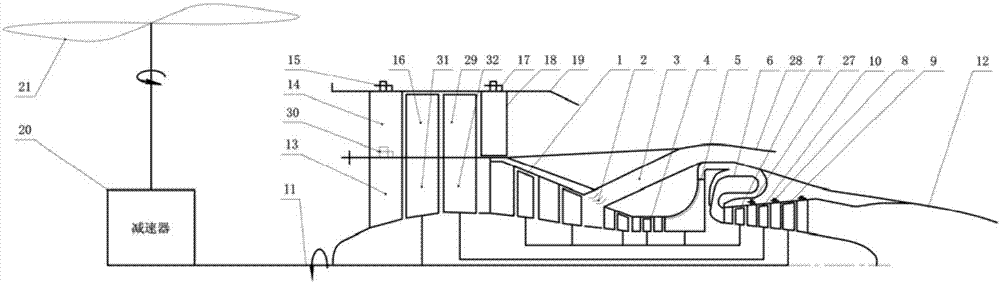
[0025] like figure 1 As shown, the turboshaft turbofan combined cycle engine is characterized in that it includes a core engine driving fan 1, and the rear part of the core engine driving fan 1 is set as two inner and outer annular flow channels, and the inner annular flow channel It communicates with the high-pressure compressor 4, and the outer annular flow channel communicates with the first duct 3 through the core machine-driven fan deflation valve 2, and the first duct 3 communicates with the first duct nozzle 28. The rear part of the high-pressure compressor 4 A centrifugal compressor 5, a recirculation annular combustor 6, a gas generator turbine 7, an adjustable medium-pressure turbine guide 27, an intermedia...


PUM


Abstract

The invention relates to the technical field of gas turbine engines, in particular to a turbo-shaft and turbo-fan combined cycle engine. The engine is characterized by comprising a core engine driving fan; an inner circular runner and an outer circular runner are arranged at the back part of the core engine driving fan; the inner circular runner communicates with a high-pressure gas compressor; the outer circular runner communicates with a first duct through a core engine driving fan gas bleed valve; a rotor of a gas generator turbine, the core engine driving fan, the high-pressure gas compressor and a rotor of a centrifugal gas compressor are coaxial; an intermediate-pressure turbine rotor, a rotor where second-stage Flade fan blades are located and a rotor where second-stage inner duct fan blades are located are coaxial; a power turbine/low-pressure turbine rotor is coaxial with rotors where first-stage Flade fan blades and first-stage inner duct fan blades are located and a power output shaft; and two rows of Flade fan rotors which rotate oppositely are arranged, so that the power capability of the fans to inflow air is enhanced, the exhaust speed of an outer duct in the turbo-fan mode of the engine is increased, and the better engine performance is acquired.

Description

technical field [0001] The invention relates to the technical field of gas turbine engines, in particular to a turboshaft turbofan combined cycle engine. Background technique [0002] The former McDonnell Douglas Helicopters proposed the canard rotor / wing (CanardRotor / Wing, CRW) concept in the early 1990s. It uses the top rotor to generate lift just like an ordinary helicopter when it takes off, and turns the top rotor into a fixed-wing aircraft by locking the top rotor when cruising at high speed (up to 700 km / h). This kind of aircraft requires that the power system can generate the power required for the rotation of the rotor during the take-off phase, and at the same time be able to generate sufficient thrust during the high-speed flight phase. The aircraft concept has clear advantages over both ordinary helicopters and fixed-wing aircraft. The key to realizing the aircraft concept is the need for matching engines. The engine requires both the functions of a turboshaft...

Claims


Application Information

Patent Timeline
IPC IPC(8): F02K3/072
CPCF02K3/072
Inventor 陈玉春贾琳渊任成王文东蒋宇翔
Owner 西安觉天动力科技有限责任公司
Why Eureka
Try Eureka