Drawing-type ring-network-cabinet-cable T-type head disassembling device

A ring network cabinet and pull-out technology, which is applied in the direction of equipment for connecting/terminating cables, can solve problems such as damage to the cabinet body and T-shaped joints, inconvenient cable maintenance, and inconvenient operation, so as to improve the efficiency of disassembly and maintenance and reduce Labor intensity, easy storage effect

Active Publication Date: 2017-07-28
海南电网有限责任公司海口供电局工会委员会
View PDF5 Cites 5 Cited by
  • Summary
  • Abstract
  • Description
  • Claims
  • Application Information

AI Technical Summary

Problems solved by technology

[0003] Aiming at the current stage, the cable T-joint can only be withdrawn manually, and there is no tool for removing the formed cable T-joint, which will cause inconvenience to cable maintenance, easily cause damage to the cabinet and T-joint, complex structure, high cost, and inconvenient operation , poor safety, and the problem of laborious disassembly, the present invention provides a pull-type ring network cabinet cable T-head remover that is easy to operate, time-saving, labor-saving, and safe. It includes a tubular base, The pressing piece, at least three arc claw hooks and the driving piece, the tubular base includes at least two support frames that are equally divided into circular arcs, a tooling plate and an annular positioning sleeve, and the support frame is arranged in parallel between the tooling plate and the ring Between the positioning sleeves, one end of the support frame is fixedly connected with the toolin

Method used


Image

  • Drawing-type ring-network-cabinet-cable T-type head disassembling device
  • Drawing-type ring-network-cabinet-cable T-type head disassembling device
  • Drawing-type ring-network-cabinet-cable T-type head disassembling device

Examples


Embodiment Construction

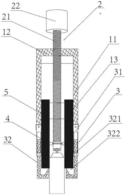
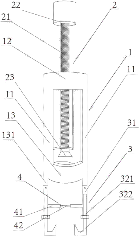
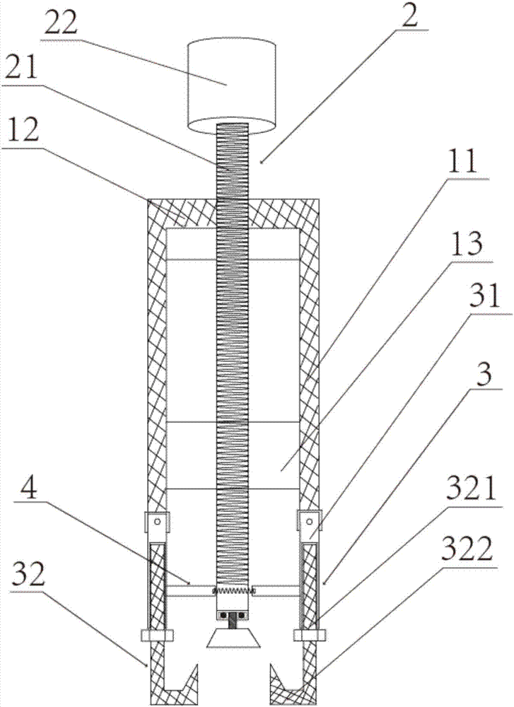
[0022] The present invention will be further elaborated below in conjunction with accompanying drawing, wherein, the direction of the present invention is with figure 1 as standard.

[0023] Such as Figure 1 to Figure 4 As shown, the pull-out type ring network cabinet cable T-head remover of the present invention includes a tubular base 1, a top pressure piece 2, an arc claw hook 3, an annular connector 4, a driver and a cable T-head 5, in.

[0024] The tubular base 1 is used to trap and position the cable T-head 5 that needs to be disassembled. The tubular base 1 is made of stainless steel or light-weight, high-strength aluminum alloy. The tubular base 1 includes at least two arc-shaped Equally divided support frame 11, tooling plate 12 and annular positioning sleeve 13, two support rods 11 are arranged vertically, tooling plate 12 is made of steel plate with a thickness of 30 mm and a diameter of 180 mm, tooling plate 12 and annular positioning sleeve 13 are all horizonta...


PUM

PropertyMeasurementUnit
Diameteraaaaaaaaaa

Abstract

The invention discloses a drawing-type ring-network-cabinet-cable T-type head disassembling device. The disassembling device comprises a tubular pedestal, a top pressing component, at least three arc claw drag hooks, an annular connecting component and a driving component. The tubular pedestal comprises at least two support frames, a tooling disc and an annular positioning sleeve. The tooling disc is provided with a threaded hole. The top pressing component comprises a rotation screw. The rotation screw is provided with an external thread which is cooperated with the threaded hole of the tooling disc. One end of the rotation screw passes through the threaded hole of the tooling disc and is inserted into the annular positioning sleeve. Each arc claw drag hook comprises a screw joint sleeve rod and a drag hook. The screw joint sleeve rod is hinged to the annular positioning sleeve. The drag hook carries out screw joint with the screw joint sleeve rod through engaged cooperation of an external thread of a pull bar handle and an internal thread of an axial through hole of the screw joint sleeve rod. The annular connecting component is formed through connecting three arc connecting components in series by three arc springs. The arc connecting components are connected to a central section of the screw joint sleeve rod so that the drag hook and a T-type head are tightly contacted and unhooking is not easy to generate. The structure is simple, and operation and carrying are convenient, timesaving, laborsaving and safe.

Description

technical field [0001] The invention relates to a dismantling tool, in particular to a pull-out type ring network cabinet cable T-shaped head dismantler. Background technique [0002] As we all know, due to the long-term operation of the 10kV cable terminal T-joints in the switch cabinets and ring network cabinets used in the power supply industry, the cable silicone grease is dry and difficult to pull out, and the lubricating silicone grease loses its effect. In addition, the cable terminal T-joints The silicone rubber is in close contact with the insulating sleeve, which makes it very difficult to disassemble the T-joint of the cable terminal. In the process of maintenance and repair in the power industry, it is often necessary to remove the cable T-joint, but there are no special tools in the current work process, so in the process of overhauling the cable terminal T-joint, it is usually necessary to rely on manual adjustment of the T-joint For disassembly, for example, ...

Claims


Application Information

Patent Timeline
IPC IPC(8): H02G1/14
CPCH02G1/14
Inventor 王照荣刘同杨智覃郑茗元蒋卿赵孙炬董明陈大勇贝嘉鹏王浪
Owner 海南电网有限责任公司海口供电局工会委员会
Why Eureka
Try Eureka