Axial moving magnetic shielding type permanent magnetic speed regulator

A technology of permanent magnet governor and axial movement, which is applied in the direction of permanent magnet clutches/brakes, etc., which can solve the problems of large vibration, easy failure of permanent magnets, and large vibration of equipment, so as to achieve easy operation, stable and more reliable products and equipment , the effect of improving safety

Pending Publication Date: 2017-07-28
TIANJIN JIXUAN ENERY SAVING TECH CO LTD
View PDF0 Cites 6 Cited by
  • Summary
  • Abstract
  • Description
  • Claims
  • Application Information

AI Technical Summary

Problems solved by technology

[0003] The existing permanent magnet governor mainly includes cylindrical permanent magnet governor and disc permanent magnet governor. To change the effective part of the coupling between the permanent magnet rotor and the conductor rotor, and then adjust the torque, this requires a large axial space to facilitate the relative axial movement between the permanent magnet rotor and the conductor rotor; and the disc permanent magnet The speed governor adjusts the torque by adjusting the air gap between the disc-shaped permanent magnet rotor and the conductor rotor, and then realizes the speed regulation of the load. It also requires a large axial space to adjust the air gap. The product shaft The size of the axis is large, which brings great inconvenience to the site transformation; in addition, when the speed is adjusted, the permanent magnet rotor needs to be moved, the equipment cantilever is long, the vibration is large, the bearing is easy to be damaged, and the reliability of the equipment is not good; when adjusting, due to the quality of the permanent magnet rotor , large moment of inertia, easy to impact; the load of the adjustment device and the adjustment bearing are easily damaged due to excessive force; the equipment has large vibration, high heat generation, and the permanent magnet is easy to fail; at the same time, it is necessary to overcome the effect of large permanent magnetic attraction when adjusting the air gap
This makes it difficult to apply in some places with limited space

Method used


Image

  • Axial moving magnetic shielding type permanent magnetic speed regulator
  • Axial moving magnetic shielding type permanent magnetic speed regulator
  • Axial moving magnetic shielding type permanent magnetic speed regulator

Examples


Embodiment

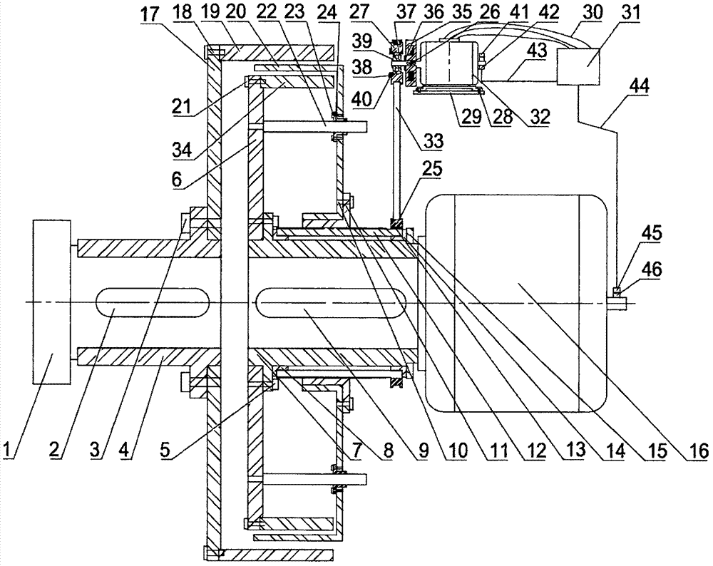
[0039] The axially moving magnetically shielded permanent magnet governor of this embodiment includes a cylindrical conductor rotor 19, a permanent magnet rotor 34 arranged on the inner periphery of the cylindrical conductor rotor 19, and a permanent magnet rotor 34 arranged between the conductor rotor 19 and the permanent magnet rotor 34. The axial movement of the magnetic shielding mechanism.

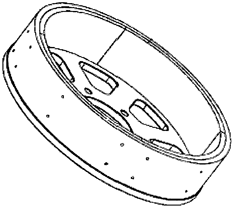
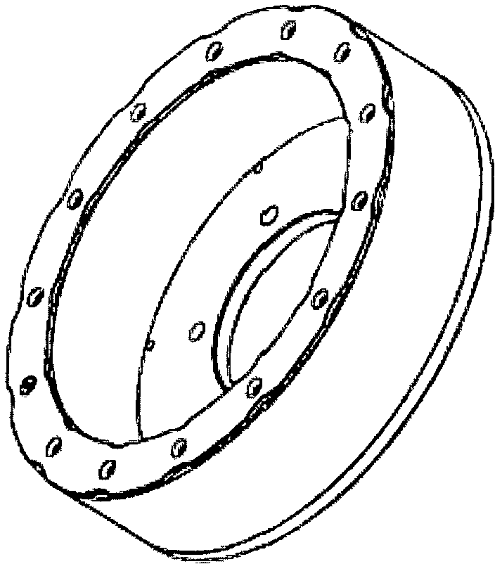
[0040] The cylindrical conductor rotor 19 is installed on the load shaft through the load coupling, and the outer circumference of the cylindrical conductor rotor 19 is equipped with a copper conductor ring, such as figure 2 shown. Among them, the permanent magnet rotor 34 is installed on the motor drive shaft through the drive shaft coupling, and the permanent magnet rotor 34 is provided with permanent magnets uniformly distributed along the circumference, and its schematic diagram is as follows image 3 shown. There is an air gap between the conductor rotor 19 and the permanent m...


PUM


Abstract

The invention discloses an axial moving magnetic shielding type permanent magnetic speed regulator. The speed regulator comprises a conductor rotor, a permanent magnetic rotor and an axial moving magnetic shielding mechanism. The axial moving magnetic shielding mechanism comprises an axial shielding structure and a magnetic flux adjusting structure. The axial shielding structure is connected with the magnetic flux adjusting structure. Axial movement of the magnetic flux adjusting structure is achieved through screws, nuts and a transmission mechanism of guide rods. By applying the magnetic shielding principle, the axial position of the axial shielding structure is adjusted. Thus, compared with the adjustment of the whole permanent magnetic rotor, the axial force to be overcome is greatly reduced, the output torque of the magnetic flux adjusting structure is greatly reduced, and the whole adjusting structure is quite simple and small.

Description

technical field [0001] The invention belongs to the technical field of permanent magnet speed regulation, in particular to an axially moving magnetic shield type permanent magnet speed regulator. Background technique [0002] In large-scale mining, petrochemical, electric power and metallurgy industries, due to the need for energy saving and environmental protection, permanent magnet speed control devices are more and more widely used. The permanent magnet speed control device can adapt to various harsh environments, including places with large grid voltage fluctuations, serious harmonics, flammable, explosive, humid, dusty, etc., and can adjust the speed of the load online to meet the actual operation needs of the system and realize speed regulation Energy saving, speed regulation range 0-98%, energy saving rate 10%-65%. When working, the motor drives the conductor rotor of the permanent magnet governor to rotate, and the copper conductor on the conductor rotor cuts the ma...

Claims


Application Information

Patent Timeline
IPC IPC(8): H02K49/10
CPCH02K49/10
Inventor 柳志明
Owner TIANJIN JIXUAN ENERY SAVING TECH CO LTD
Why Eureka
Try Eureka