Electric appliance main contactor management circuit and method

A main contactor and circuit technology, which is applied in the field of vehicle control, can solve the problems of system efficiency reduction, system reliability reduction, noise, etc., and achieve the effect of prolonging service life and no oxidation of surface resistance

Inactive Publication Date: 2017-07-28
友信宏科新能源(徐州)有限公司
View PDF4 Cites 1 Cited by
  • Summary
  • Abstract
  • Description
  • Claims
  • Application Information

AI Technical Summary

Problems solved by technology

[0004] The embodiment of the present invention provides a main contactor management circuit and method of an electrical appliance, aiming at solving the problem of using an electrical appliance as the main contactor in the prior art. The system reliability is reduced, and it will also lead to a decrease in system efficiency, and there will be noise when breaking, which will affect the driving experience of electric vehicles.

Method used


Image

  • Electric appliance main contactor management circuit and method
  • Electric appliance main contactor management circuit and method
  • Electric appliance main contactor management circuit and method

Examples


Embodiment 1

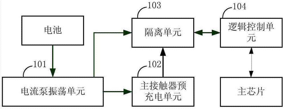
[0050] figure 1 A specific structural block diagram of the main contactor management circuit of the electrical appliance provided by Embodiment 1 of the present invention is shown. For the convenience of description, only the parts related to the embodiment of the present invention are shown. In this embodiment, the main contactor management circuit of the electrical appliance includes: a battery, a current pump oscillation unit 101, a main contactor pre-charging unit 102, an isolation unit 103, a logic control unit 104 and a main chip, wherein,

[0051] The current pump oscillating unit 101 is used to amplify the current through the push-pull circuit to continuously charge the first capacitor, and keep the voltage value of the second capacitor at the output end of the first capacitor not lower than a preset value;

[0052] The main contactor pre-charging unit 102 is used to use the transistor as the main contactor when charging the second capacitor when powered on, and realiz...

Embodiment 2

[0073] Image 6 It shows the implementation process of the main contactor management method of electrical appliances provided by Embodiment 2 of the present invention, and the details are as follows:

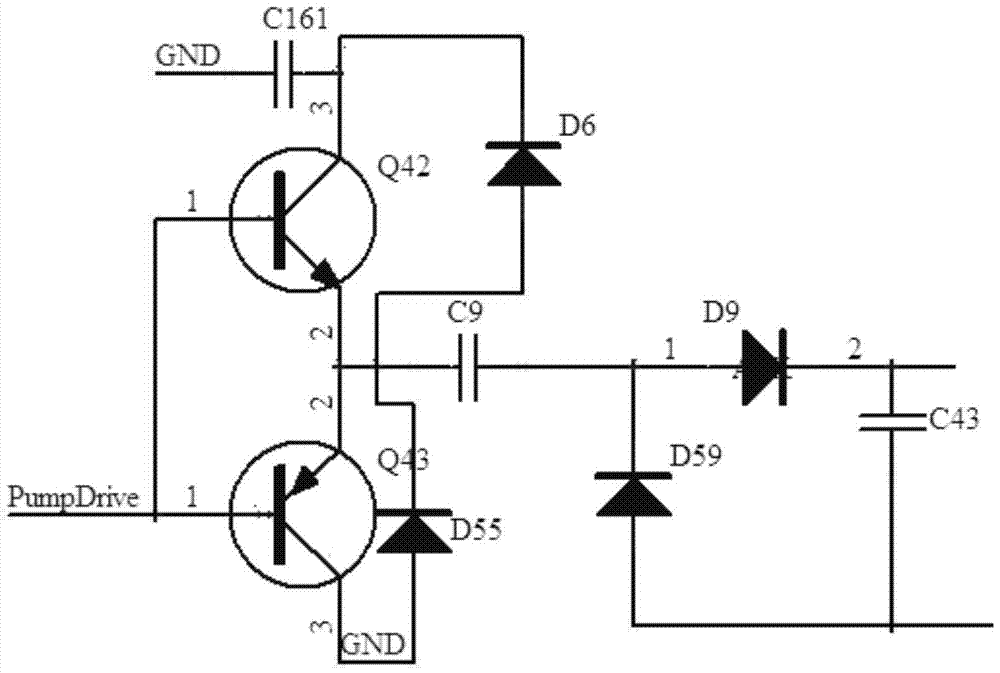
[0074] In step S601 , the push-pull circuit performs current amplification to continuously charge the first capacitor, and keeps the voltage value of the second capacitor at the output end of the first capacitor not lower than a preset value.

[0075] In this embodiment, this step consists of figure 2 The circuit shown is completed, specifically, the PNP transistor Q42 and the NPN transistor Q43, the base of the PNP transistor Q42 and the base of the NPN transistor Q43 are respectively connected to the input electrical signal, and the collector of the PNP transistor Q42 is connected to the third parallel connection. One end of the capacitor C161 is connected to the negative pole of the first diode D6, the emitter of the PNP transistor Q42 is respectively connected to the emitt...


PUM


Abstract

The invention provides an electric appliance main contactor management circuit and method, and is applied to the technical field of vehicle control. The circuit comprises a current pump oscillation unit, a main contactor pre-charge unit, an isolation unit and a logic control unit, wherein the current pump oscillation unit is used for performing current amplification through a push-pull circuit to continuously charge a first capacitor and enabling a voltage value of a second capacitor at an output end of a first capacitor to be not less than a preset value; the main contactor pre-charge unit is used for taking a transistor as a main contactor when charging the second capacitor after being powered on and implementing charge control on the second capacitor by switching on the main contactor; the isolation unit is used for isolating the logic control unit from high voltage of the main contactor in order to protect a low-voltage circuit; and the logic control unit is used for performing logic control on the isolation unit through a main chip. According to the electric appliance main contactor management circuit and method, the transistor is taken as the main contactor, management of the transistor as the main contactor is implemented by isolation power supply control logic, and high-power power supply circuit off-on control is implemented.

Description

technical field [0001] The invention belongs to the technical field of vehicle control, and in particular relates to a main contactor management circuit and method of electrical appliances. Background technique [0002] Traditional electrical appliances are a type of components or devices that manually or automatically switch on and off circuits to achieve switching, control, protection, detection, transformation and adjustment of circuits or non-electrical objects according to external signals and requirements, including circuit breakers. Devices, contactors, relays, solid state relays and other types. The development of electrical appliances depends on the development of the national economy and the needs of the development of modern industrial automation, as well as the research and application of new technologies, new processes, and new materials. [0003] At present, in the control system of electric vehicles, traditional electrical appliances are still generally used ...

Claims


Application Information

Patent Timeline
Patent Type & Authority Applications(China)
IPC IPC(8): H03K17/78H03K17/56
CPCH03K17/56H03K17/78
Inventor 韩彦杰李萌
Owner 友信宏科新能源(徐州)有限公司
Why Eureka
Try Eureka