Novel four-rotor unmanned aerial vehicle with mechanical arm

A four-rotor unmanned aerial vehicle, quad-rotor technology, applied in the direction of rotorcraft, unmanned aerial vehicle, fuselage, etc., to achieve the effect of reducing the difficulty of operation, increasing the working range and operation ability

Pending Publication Date: 2017-08-01
GUILIN UNIV OF ELECTRONIC TECH
View PDF7 Cites 11 Cited by
  • Summary
  • Abstract
  • Description
  • Claims
  • Application Information

AI Technical Summary

Problems solved by technology

[0006] However, complex operations at high altitudes, operations in dangerous areas, and rescue operations such as high-altitude fires and earthquakes have not been involved in the development of the industry.
Due to the limitation ...

Method used


Image

  • Novel four-rotor unmanned aerial vehicle with mechanical arm
  • Novel four-rotor unmanned aerial vehicle with mechanical arm
  • Novel four-rotor unmanned aerial vehicle with mechanical arm

Examples


Embodiment 1

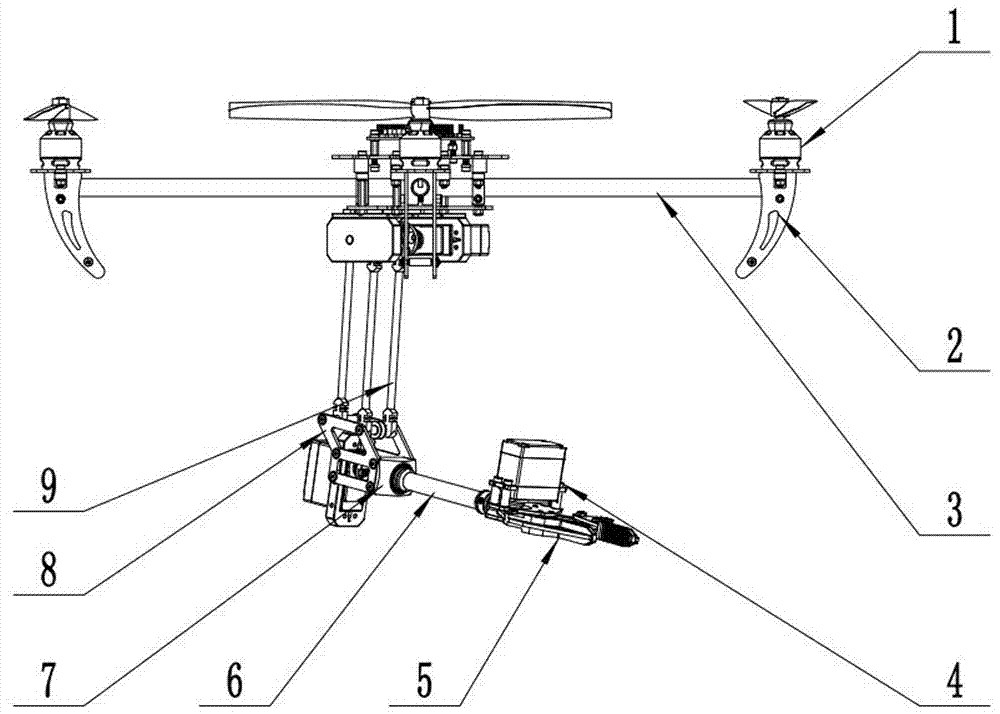
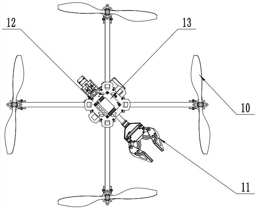
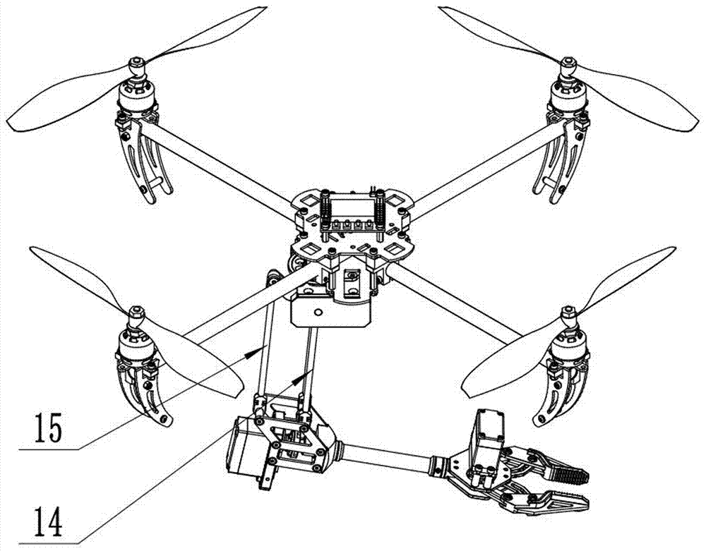
[0030] A new quadrotor UAV with arms is composed of a quadrotor UAV part, an image transmission part, a multi-degree-of-freedom mechanical arm part, a mechanical claw part and a pan-tilt camera part, wherein:

[0031] The four-rotor UAV part is composed of the main structure carbon cross bracket 3, the upper platform 12, the lower platform, the base, the motor 1 and the rotor. The two main structure carbon crosses 3 are fastened to each other through the groove in the middle, Fastening increases the contact area of ​​the carbon cross of the main structure, and the flight stability is greatly enhanced; the upper gimbal 12 and the lower gimbal are connected with pins and bolts, and the main circuit board and other components are placed in the hollow part of the upper and lower gimbals. The upper cloud platform 12 is equipped with image transmission part components, and the lower platform is equipped with a multi-degree-of-freedom mechanical arm part. The motor 1 includes motor A...

Embodiment 2

[0042] The present invention is mainly used for tasks that cannot be completed manually under complex conditions. UAVs with mechanical arms are used to realize task requirements, and complex tasks such as water resource sampling and soil sampling are performed in polluted areas. Specific examples : Water sampling in polluted areas.

[0043] Secondly, it can also be used in high-rise fire rescue. Through its multi-degree-of-freedom mechanical claws, a rescue network can be established through collaborative work in the air, so that the trapped people in the higher floors can pass through the established rescue network. Rescued safely.

[0044] In high-altitude operations, due to the wide range of multi-free manipulators, more actions can be completed, which can realize the maintenance of high-altitude facilities such as wires and cables. At the same time, sensors (sonic waves, infrared rays, etc.) can be installed to detect the walls of high-rise buildings. Whether there are cr...


PUM

PropertyMeasurementUnit
Pitch angleaaaaaaaaaa

Abstract

The invention discloses a novel four-rotor unmanned aerial vehicle with a mechanical arm. The novel four-rotor unmanned aerial vehicle comprises a four-rotor unmanned aerial vehicle part and is characterized in that the novel four-rotor unmanned aerial vehicle further comprises an image transmission part, a multi-degree-of-freedom mechanical arm part, a mechanical gripper part and a cloud deck photographing part which are connected with the four-rotor unmanned aerial vehicle part correspondingly. According to the novel four-rotor unmanned aerial vehicle with the mechanical arm, an existing four-rotor unmanned aerial vehicle structure is integrated rationally, an original upper and lower plastic shell wrapped structure is changed, a carbon square tube is adopted, a double-layer cloud deck is additionally installed, the upper layer cloud deck is provided with camera equipment, and the lower layer cloud deck is provided with the mechanical arm, so that the idea that the multi-degree-of-freedom mechanical arm is additionally installed to realize development in more areas of the four-rotor unmanned aerial vehicle and operation in complex artificial environment in addition to an early warning function based on the original camera environment.

Description

technical field [0001] The invention relates to the field of unmanned aerial vehicles, in particular to a novel four-rotor unmanned aerial vehicle with arms. Background technique [0002] The quadrotor unmanned aerial vehicle is a "saucer" aircraft with a novel structural layout and unique flight mode. It uses aerodynamics to overcome its own weight. It can fly autonomously or remotely, and can carry a certain load. It can be equipped with special instruments to achieve some specific functions. It can take off and land vertically on the spot, can perform manual and automatic flight, and can realize fixed-point hovering and fixed-track flight in the air. The air monitoring function is realized through the on-board camera equipment, and the related software of the ground station realizes video reception. [0003] The four-rotor unmanned aerial vehicle is an aircraft with four propellers and the four propellers are in a cross-shaped structure. The opposite four-rotors have th...

Claims


Application Information

Patent Timeline
IPC IPC(8): B64C27/08B64C1/00B64C1/06B64D47/00B64D47/08
CPCB64C1/00B64C1/061B64C27/08B64D47/00B64D47/08B64C2001/0054B64U50/19B64U10/10B64U2101/00
Inventor 周祖鹏李赫刘旭锋
Owner GUILIN UNIV OF ELECTRONIC TECH
Why Eureka
Try Eureka