Conveying device for lead ingots at discharging port

A technology of conveying device and discharge port is applied in the field of lead ingot conveying device at the discharge port, which can solve the problems of increasing the difficulty of lead ingots, reducing production efficiency, and the angle deviation of lead ingots, avoiding manual manual control and reducing work efficiency. , the effect of convenient transportation

Active Publication Date: 2017-08-01
LUOYANG PLUS AUTOMATION TECH EQUIP CO LTD
View PDF3 Cites 6 Cited by
  • Summary
  • Abstract
  • Description
  • Claims
  • Application Information

AI Technical Summary

Problems solved by technology

[0002] Lead ingots are divided into large ingots and small ingots. The small ingots are rectangular trapezoidal with bundling grooves at the bottom and protruding ears at both ends. It is mainly used in the manufacture of batteries, paints, warheads, welding materials, chemical lead salts, cable sheaths, bearing materials, caulking materials, Babbitt alloys and X-ray protective materials, etc.; during the production and transportation of lead ingots, in When the lead ingot is placed on the conveyor belt, it will more or less cause the lead ingot to deviate at a certain angle. If no adjustment is made, it will increase the difficulty of removing the lead ingot from the conveyor belt and reduce production efficiency

Method used


Image

  • Conveying device for lead ingots at discharging port
  • Conveying device for lead ingots at discharging port
  • Conveying device for lead ingots at discharging port

Examples


Embodiment Construction

[0018] The following will clearly and completely describe the technical solutions in the embodiments of the present invention with reference to the accompanying drawings in the embodiments of the present invention. Obviously, the described embodiments are only some, not all, embodiments of the present invention.

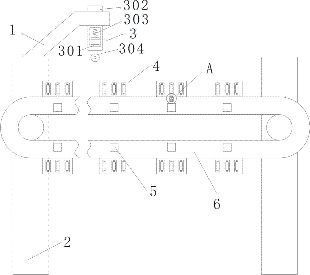
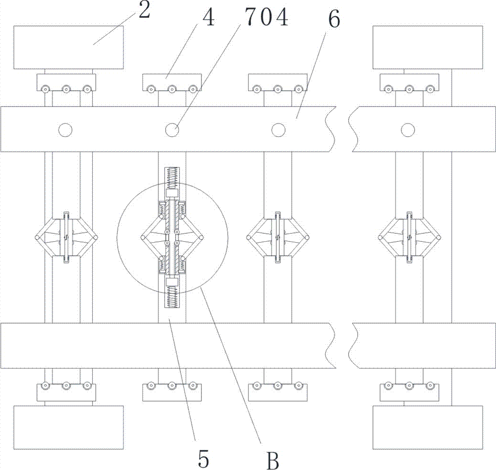
[0019] refer to Figure 1-5 , a lead ingot conveying device at the discharge port, comprising two groups of first straight rods 2, rotating shafts are connected between each group of two first straight rods 2, and the two rotating shafts are connected by two conveyor belts 6, the first straight rods One side of the rod 2 is provided with a motor, the output end of the motor is connected with one of the rotating shafts, and the top of one of the first straight rods 2 is connected with a curved rod 1, and a travel switch 3 is arranged on the curved rod 1, and the travel switch 3 includes a The mounting rod 302 that the rod 1 is threaded, the mounting rod 302 is provide...


PUM


Abstract

The invention discloses a conveying device for lead ingots at a discharging port. The conveying device comprises two groups of first straight rods, wherein a rotating shaft is rotationally connected between two first straight rods of each group, the two rotating shafts are connected through two conveying belts, a motor is arranged on one sides of the first straight rods, the output end of the motor is connected with one of the rotating shafts, the top end of one of the first straight rods is connected with a crank rod, a travel switch is arranged on the crank rod, the opposite sides of the conveying belts are provided with second straight rods, and a connecting pipe is arranged between every two corresponding second straight rods. According to the conveying device, the structure is simple, pressure-operated switches are triggered by means of gravity of the lead blocks, and extrusion plates are controlled to extrude the lead blocks to adjust the inclined angles of the lead blocks in the process of placing the lead blocks on the conveying belts, so that the lead blocks are perpendicular to the conveying belts and convenient to transfer; and meanwhile, the travel switch is arranged, and therefore fixed-point parking of the lead blocks is realized, and the problem that due to the manual control, the burden of workers is increased and the working efficiency is reduced is avoided.

Description

technical field [0001] The invention relates to the technical field of conveying equipment, in particular to a lead ingot conveying device at a discharge port. Background technique [0002] Lead ingots are divided into large ingots and small ingots. The small ingots are rectangular trapezoidal with bundling grooves at the bottom and protruding ears at both ends. It is mainly used in the manufacture of batteries, paints, warheads, welding materials, chemical lead salts, cable sheaths, bearing materials, caulking materials, Babbitt alloys and X-ray protective materials, etc.; during the production and transportation of lead ingots, in When the lead ingots are placed on the conveyor belt, the lead ingots will more or less have a certain angle offset. If no adjustment is made, it will increase the difficulty of removing the lead ingots from the conveyor belt and reduce production efficiency. Contents of the invention [0003] The purpose of the present invention is to solve t...

Claims


Application Information

Patent Timeline
Patent Type & Authority Applications(China)
IPC IPC(8): B65G47/24B65G43/08
CPCB65G43/08B65G47/24B65G2203/0266
Inventor 翟胜宇翟胜辉彭锴付红闯李红社翟维华
Owner LUOYANG PLUS AUTOMATION TECH EQUIP CO LTD
Why Eureka
Try Eureka