Thermal energy machine with flow guide devices in the diffusor

A technology of diffuser and thermal energy, which is applied to components of pumping devices for elastic fluids, gas turbine devices, machines/engines, etc., and can solve problems such as low efficiency of turbines

Inactive Publication Date: 2017-08-01
SIEMENS AG
View PDF6 Cites 0 Cited by
  • Summary
  • Abstract
  • Description
  • Claims
  • Application Information

AI Technical Summary

Problems solved by technology

This deviation in direction can have a negative effect on the overall flow behavior of the air mass flow, as a result of which there is often only limited uniform inflow, in particular into the inflow channels, so that the turbine as a whole works inefficiently

Method used


Image

  • Thermal energy machine with flow guide devices in the diffusor
  • Thermal energy machine with flow guide devices in the diffusor

Examples


Embodiment Construction

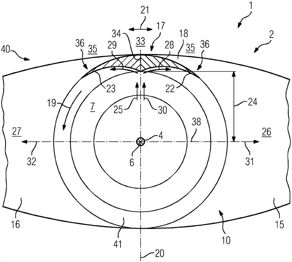
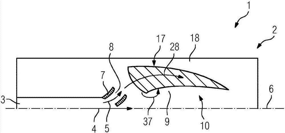
[0037]figure 1 with figure 2 The turbomachine 1 shown at least in part is a gas turbine 2 .

[0038] Here, the turbine 1 essentially comprises a compressor 3 for compressing an air mass flow 5 flowing in an axial flow direction 4 (see figure 2 ) (marked with numbers for exemplary purposes only).

[0039] Here, the compressor 3 is arranged concentrically around a longitudinal center axis 6 of the turbine, which likewise represents the machine axis.

[0040] Downstream of the compressor 3 , ie arranged downstream of the compressor 3 in the flow direction 4 , a diffuser 7 is arranged axially upstream and downstream, wherein the diffuser 7 has a diffuser that is formed concentrically around the longitudinal center axis 6 of the turbine. The diffuser outlet 8 from which the air mass flow 5 exits is correspondingly decelerated into the diffuser outlet region 9 .

[0041] The diffuser outlet area 9 is delimited in particular by the inner casing 10 of the turbine 1 and ultimately...


PUM


Abstract

The invention relates to a thermal energy machine (1), in particular a gas turbine (2), comprising a compressor (3) for compressing an air mass flow (5) flowing along the machine longitudinal central axis (6) in an axial flow direction (4), a diffusor (7) connected axially downstream of the compressor (3), and two opposing silo combustion chambers which are arranged further outward radially and into which the air mass flow (5) exiting the diffusor (7) can flow by means of a diffusor exit region (9) which is formed in a corresponding manner by housing parts (10) of the thermal energy machine (1). The diffusor exit region (9) opens radially into supply channels (15, 16) leading to the silo combustion chambers, and the diffusor exit region (9) is designed such that the air mass flow (5) exiting the diffusor (7) is discharged asymmetrically in order to be supplied homogenously to the supply channels (15, 16) of the silo combustion chambers.

Description

technical field [0001] The invention relates to a thermal energy machine, in particular a gas turbine, with a compressor for compressing an air mass flow flowing in an axial flow direction along the longitudinal center axis of the machine, with a diffuser connected axially downstream of the compressor, And with two opposite, radially further outwardly arranged silo combustion chambers, into which the air mass flow escaping from the diffuser can flow out via a diffuser outlet region formed correspondingly by the housing parts of the heat engine and at the silo combustion chamber the diffuser outlet region merges radially into an inflow channel leading to the silo combustion chamber. Background technique [0002] A general heat engine is also generally known as a gas turbine in the prior art, in which a diffuser arranged downstream of the compressor or of the compressor outlet in the axial direction of flow serves especially on the one hand for the air mass flow The delay and...

Claims


Application Information

Patent Timeline
Patent Type & Authority Applications(China)
IPC IPC(8): F01D25/30F02C3/14F04D29/54F01D9/02F23R3/04
CPCF01D9/023F01D25/30F02C3/14F05D2240/12F23R3/04
Inventor F·富克斯M·黑克劳N·赫尔佐克P·T·马维罗马蒂斯S·穆特克J·米尔M·普鲁斯R·雷克尔特J·施派泽R·沃尔塔特
Owner SIEMENS AG
Why Eureka
Try Eureka