Terminal for connectors
A connector and terminal technology, applied in the direction of connection, conductive connection, contact parts, etc., can solve the problems of low corrosion resistance and corrosion of metal base materials, and achieve the effect of improving corrosion resistance
- Summary
- Abstract
- Description
- Claims
- Application Information
AI Technical Summary
Problems solved by technology
Method used
Image

Examples
Embodiment 1
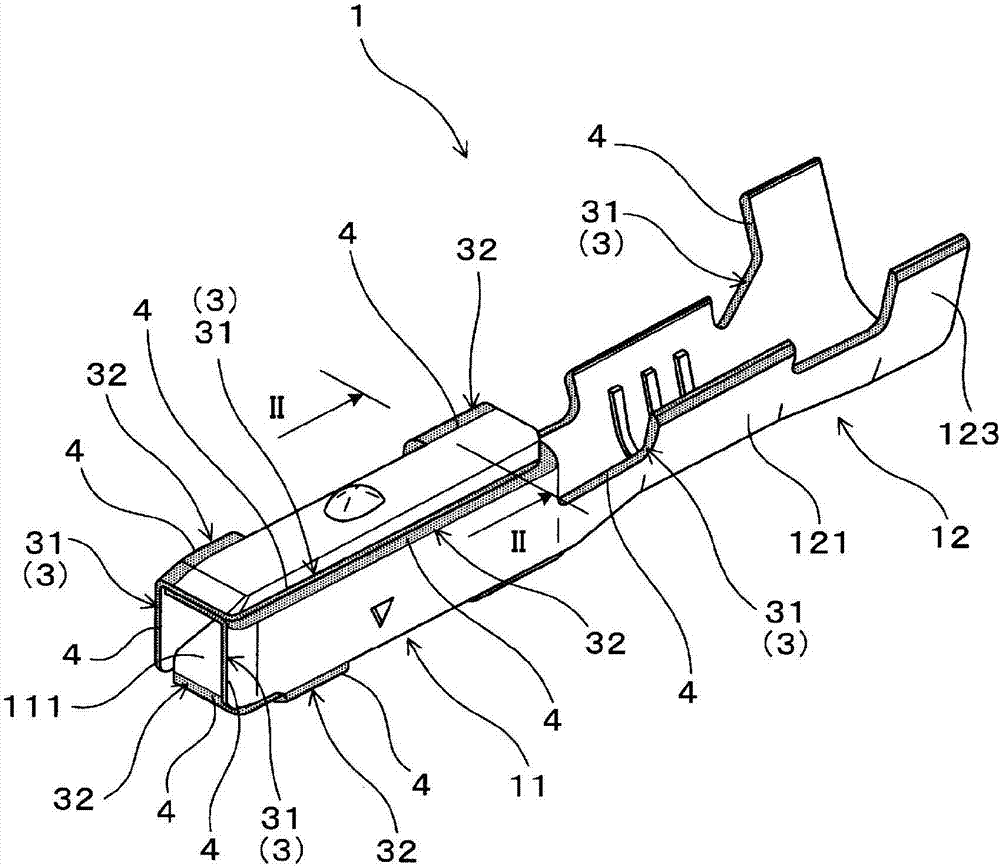
[0031] use figure 1 and figure 2 The connector terminal of the first embodiment will be described. Such as figure 1 and figure 2 As shown, the connector terminal 1 is composed of a terminal material 2 having a plated film 22 on the surface of a metal base material 21 .
[0032] In this example, specifically, as figure 1 As shown, the connector terminal 1 is a female terminal, and is used in a connector (not shown) included in a wiring harness for an automobile. More specifically, the connector terminal 1 has a rectangular cylindrical fitting portion 11 and a cylindrical portion 12 connected to the fitting portion 11 .
[0033] An anode piece portion included in a male terminal (not shown) serving as a counterpart terminal to be electrically connected is inserted into the fitting portion 11 . Inside the fitting portion 11 , an elastic contact piece 111 is formed by folding the bottom plate portion of the fitting portion 11 inward and rearward. A contact part (not sh...
Embodiment 2
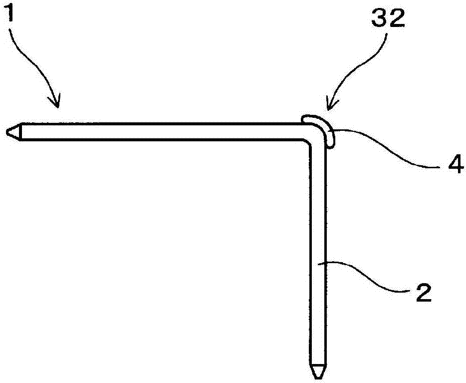
[0043] use image 3 and Figure 4 The connector terminal of the second embodiment will be described. Such as image 3 and Figure 4 As shown, the terminal 1 for a connector of this example is a pin terminal and has a substantially "L-shaped" terminal shape. Specifically, the terminal 1 for a connector is used in a substrate connector (not shown) applied to a PCB.
[0044] More specifically, the connector terminal 1 of this example is produced through the following steps: cutting the linear terminal material 2 into a predetermined length, and performing bending processing of bending 90° at the middle part of the cut piece to form the bent portion 32 . In addition, the terminal 1 for a connector can also be produced through the following steps: punch out the plate-shaped terminal material 2 to form a punched piece, and perform a bending process of bending 90° at the middle part of the punched piece to form a bent portion. 32.
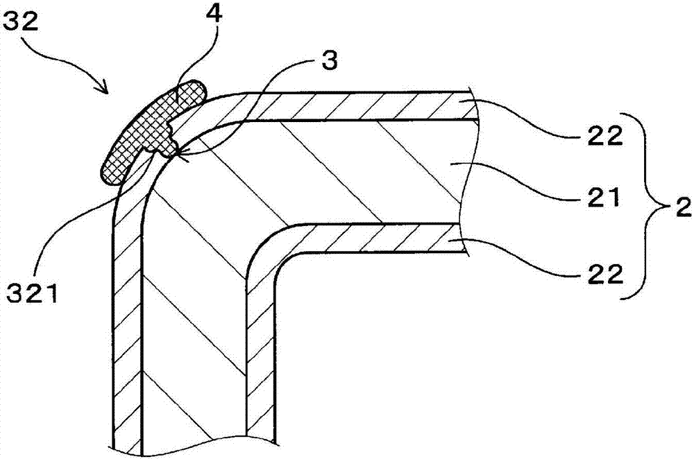
[0045] In the terminal 1 for a connector, th...
experiment example
[0048] Hereinafter, it demonstrates more concretely using an experimental example.
[0049] Prepare a plate-shaped terminal material in which a Sn plating film (thickness 1.2 μm) composed of reflow-plated Sn is formed on the surface of a plate-shaped metal base material (plate thickness 0.3 mm), wherein the mass % of the metal base material contains 0.4% C , and the remainder is composed of Fe and unavoidable impurities.
[0050] Next, a raw material sheet capable of constituting a 0.64-type female terminal shape is punched out from the plate-shaped terminal material by a punching machine, and the raw material sheet is bent to obtain a 0.64-shaped female terminal. In addition, the metal base material was exposed on the punched out surface of the obtained female terminal. In addition, the plated film of the obtained female terminal was cracked at a part of the bent portion, and the base metal was exposed at the cracked portion.
[0051] A coating film was formed by applying a...
PUM
 Abstract
Description
Claims
Application Information
 - R&D
- Intellectual Property
- Life Sciences
- Materials
- Tech Scout
- Unparalleled Data Quality
- Higher Quality Content
- 60% Fewer Hallucinations
Browse by: Latest US Patents, China's latest patents, Technical Efficacy Thesaurus, Application Domain, Technology Topic, Popular Technical Reports.
© 2025 PatSnap. All rights reserved.Legal|Privacy policy|Modern Slavery Act Transparency Statement|Sitemap|About US| Contact US: help@patsnap.com