Tool clamping device and tool clamping equipment

A clamping device and tooling technology, used in metal processing equipment, positioning devices, mechanical equipment, etc., can solve the problems of time-consuming and labor-intensive efficiency, and achieve the effect of improving stability and reliability, convenient operation and high clamping efficiency.

Pending Publication Date: 2017-08-04
BEIJING SHENGFEIFAN ELECTRONIC SYST TECH DEV CO LTD
View PDF9 Cites 8 Cited by
  • Summary
  • Abstract
  • Description
  • Claims
  • Application Information

AI Technical Summary

Problems solved by technology

[0003] In order to solve the time-consuming, labor-intensive and low-efficiency problems of the existing clamping methods, the present invention provides a tool clamping device and tool clamping equipment, which have the advantages of simple structure, convenient operation, high clamping efficiency and high stability. , and use the dead point position of the transmission mechanism to improve the stability and reliability of the workpiece clamping

Method used


Image

  • Tool clamping device and tool clamping equipment
  • Tool clamping device and tool clamping equipment
  • Tool clamping device and tool clamping equipment

Examples


no. 1 example

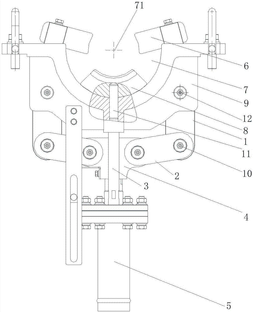
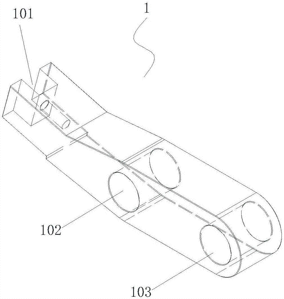
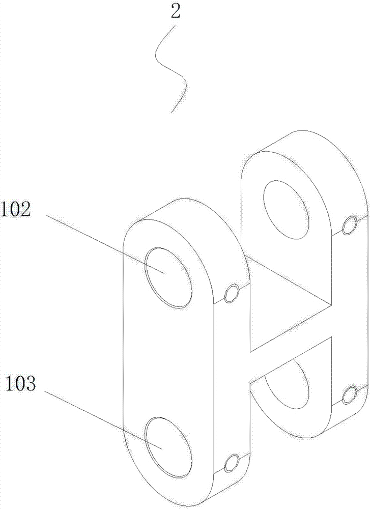
[0025] A tool clamping device, which includes a clamping seat 9 with a clamping port 7 and a power output mechanism 5 that continuously outputs stable power. The output end of the power output mechanism 5 is connected to a drive joint 4, and the power output mechanism 5 drives The driving joint 4 moves up and down, and the clamping seat 9 is connected with the clamping rod 1 through the rotating shaft 12. The height of the clamping rod 1 is greater than the height of the driving joint 4. Between the clamping rod 1 and the driving joint 4 A connecting rod 2 is provided, and the two ends of the connecting rod 2 are respectively rotatably connected to the driving joint 4 and the clamping rod 1 through the pin shaft 10. In addition, the end of the clamping rod 1 away from the connecting rod 2 and the inner wall of the clamping port 7 form a clamping Hold Space 71. The rotating shaft 12 and the pin shaft 10 are arranged in parallel, that is, the rotating direction of the clamping r...

no. 2 example

[0033]This second embodiment makes the following improvements on the basis of the first embodiment: when the drive joint 4 moves to the highest point, the drive joint 4 and the connecting rod 2 are located on the same straight line; 2 When it is on the same straight line, the drive joint 4 can no longer move up, which means that there is no need for the user to adjust the stroke of the drive joint 4, only when the drive joint 4 cannot continue to move up, the drive joint 4 has been realized. The connecting rods 2 are located on the same straight line, so that the force transmitted from the connecting rod 2 to the drive joint 4 cannot produce a torque that makes the drive joint 4 rotate, which also forms a dead point, which means that the user does not need to specially adjust the drive The size of the upward stroke of the joint 4 can form a dead point, which can make the operation more convenient and quick.

[0034] In this embodiment, when the drive joint 4 moves up to the hi...

no. 3 example

[0037] In addition, because the sizes of the workpieces are different, if the size of the workpieces is too small, when the drive joint 4 moves up to the highest position, the workpieces still cannot be fixed in time. For this problem, further optimization is carried out in this embodiment: according to figure 1 and figure 2 As shown, the end of the clamping rod 1 away from the connecting rod 2 is detachably fixed with a clamping block 6, and the inner wall of the clamping opening 7 is detachably fixed with a workpiece bracket 8, through the clamping block 6 and the workpiece bracket 8 Compressing the clamping space 71 formed by the clamping rod 1 and the clamping opening 7 realizes the clamping and fixing of smaller workpieces.

[0038] In this embodiment, the workpiece is clamped by using the workpiece bracket 8 and the clamping block 6 . Therefore, the shape of the workpiece bracket 8 and the shape of the clamping block 6 can also be replaced according to the shape of th...


PUM


Abstract

The invention discloses a tool clamping device and tool clamping equipment. The tool clamping device comprises a clamping seat provided with a clamping opening and a power output mechanism continuously outputting stable powder. The output end of the power output mechanism is connected with a driving connector. The power output mechanism drives the driving connector to move up and down. The clamping seat is rotatably connected with clamping rods through rotating shafts. The heights of the positions where the clamping rods are located are larger than the height of the position where the driving connector is located. Connecting rods are arranged between the clamping rods and the driving connector. The two ends of the connecting rods are rotatably connected to the driving connector and the clamping rods through pin shafts correspondingly. The rotating shafts and the pin shafts are arranged parallelly. The ends, far from the connecting rods, of the clamping rods and the inner wall of the clamping opening form a clamping space. The clamping rods in a moving state adjust the positions to clamp a workpiece; and meanwhile by utilizing a dead point position of a transmission mechanism composed of the driving connector, the connecting rods and the clamping rods, the stability and reliability of workpiece clamping are improved.

Description

technical field [0001] The invention relates to the field of clamp positioning mechanisms in the manufacturing industry, in particular to a tool clamping device and tool clamping equipment. Background technique [0002] In industrial production, it is often necessary to perform flame cutting, laser cutting or plane milling, drilling, gear shaping and other processing procedures on very long (several meters to tens of meters or longer) polygonal workpieces. The workpiece is clamped by the host and driven to rotate. At this time, it is necessary to support and clamp the periphery of the workpiece. In addition to sufficient clamping force, the clamping of the workpiece must also ensure that the workpiece is concentric with the spindle. The previous clamping method is to manually tighten several wires around the workpiece support ring. This method is time-consuming, laborious, and inefficient. More importantly, it is difficult to control how much the screw is screwed in, and it ...

Claims


Application Information

Patent Timeline
Patent Type & Authority Applications(China)
IPC IPC(8): B23Q3/08B23K7/10B23K26/70B23F23/06
CPCB23F23/06B23K7/10B23K26/70B23Q3/082
Inventor 肖勇彭辉宁飞桑凯温玉芹
Owner BEIJING SHENGFEIFAN ELECTRONIC SYST TECH DEV CO LTD
Why Eureka
Try Eureka