
Plate sorting and conveying device

A conveying device and plate technology, applied in conveyors, conveyor objects, transportation and packaging, etc., can solve the problems of low degree of automation, easy falling of plates, waste of labor, etc., so as to avoid rigid damage, fast transportation, and improve work efficiency. The effect of efficiency

Pending Publication Date: 2017-08-04
CHENGDU ZHENZHONG ELECTRIC
View PDF6 Cites 2 Cited by
  • Summary
  • Abstract
  • Description
  • Claims
  • Application Information

AI Technical Summary

Problems solved by technology

[0003] The purpose of the present invention is to provide a board sorting and conveying device to solve the problem of low automation and labor waste caused by traditional manual transportation of boards, and the boards are easy to fall during the handling process, thereby causing damage to the boards

Method used


Image

  • Plate sorting and conveying device
  • Plate sorting and conveying device
  • Plate sorting and conveying device

Examples


Embodiment 1

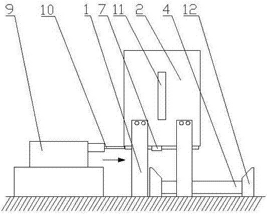
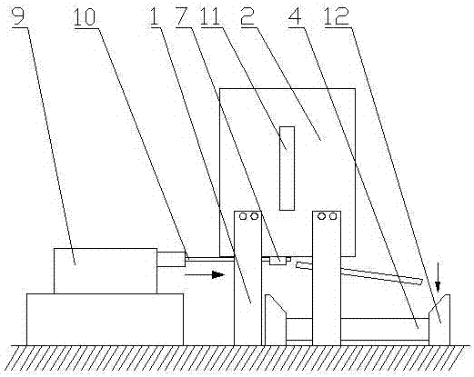
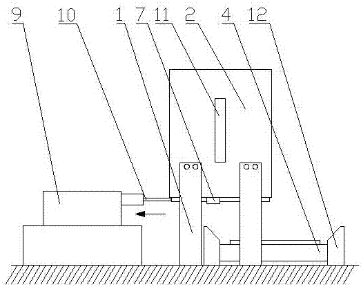
[0035] Such as figure 1 , 2 , 3 and 4, the plate sorting transmission device includes a bracket 1, a material box 2, a discharge device and a guide rail 4, the material box 2 is supported by the bracket 1, and the top of the material box 2 is provided with a feeding port. There is a discharge port 6 at the bottom, and a baffle 7 extends downward along the bottom edge of the outer wall of the material box 2. The bottom end of the baffle plate 7 extends horizontally toward the inner side of the material box 2 with a clamping plate 8, and the clamping plate 8 and A plate guide cavity is formed between the discharge ports 6; a plate horizontal push rod 10 that can push the plate to be pushed out of the plate guide cavity is arranged in the plate guide cavity, and the piston of the cylinder 9 is fixedly connected with the plate horizontal push rod 10. The distance between the clamping plate 8 and the feed port is equal to the thickness of the plate to be pushed out, and the plate ...

Embodiment 2

[0037] Such as figure 1 , 2 As shown in and 3, compared with Example 1, this embodiment optimizes the plate horizontal push rod 10, the baffle plate 7 and the clamping plate 8 constitute a fixed claw to prevent the plate from falling, and there are two fixed claws, which are respectively arranged on the material placement A set of opposite outer wall bottoms on the box 2, in this embodiment, the two fixing claws can hold the plate more stably and prevent the plate from falling.

Embodiment 3

[0039] Compared with Example 1, this embodiment optimizes the clamping plate 8, and the plate horizontal push rod 10 is located between the two fixed claws in the vertical direction. In this embodiment, when the plate horizontal push rod 10 is prevented from pushing the plate, the plate will The horizontal push rod 10 and the fixed claw touch each other, thereby damaging the plank horizontal push rod 10 or the fixed claw.


PUM


Abstract

The invention discloses a plate sorting and conveying device which comprises a support, a material containing box, a guide rail and an air cylinder. The material containing box is supported through the support. A feeding opening is formed in the top of the material containing box, and a discharging opening is formed in the bottom of the material containing box. A baffle is arranged in the manner of extending downwards along the bottom edge of the outer side wall of the material containing box. The bottom end of the baffle horizontally extends towards the middle of the discharging opening to form clamp plates. A plate guide cavity is formed among the clamp plates and the discharging opening. A plate horizontal pushing rod capable of pushing a to-be-pushed-out plate out of the plate guide cavity is arranged in the plate guide material. A piston of the air cylinder is fixedly connected with the plate horizontal pushing rod. The distance between the clamp plates and the feeding opening is equal to the thickness of the to-be-pushed-out plate. The plate horizontal pushing rod pushes the plate out of the plate guide cavity through the air cylinder. The guide rail for bearing the pushed-out plate is arranged below the plate guide cavity. The plate sorting and conveying device has the beneficial effects that the plate can be transported fast, and the situation that during manual carrying, the plate is damaged, and labor force is wasted can be avoided.

Description

technical field [0001] The invention relates to a conveying device, in particular to a plate sorting conveying device. Background technique [0002] After the plate is cut and processed, it is often carried by manpower. In the process of carrying, if there is a slight carelessness, the plate will fall down, thereby damaging the plate, and in the process of carrying, it will often cause waste of labor. Contents of the invention [0003] The purpose of the present invention is to provide a plate sorting and conveying device, which solves the problems of low automation and labor waste caused by traditional manual transport of plates, and the plates are easy to fall during the handling process, thereby causing damage to the plates. [0004] In order to solve the above-mentioned technical problems, the present invention adopts the following technical solutions: [0005] The plate sorting and conveying device includes a bracket, a material box, a guide rail and an air cylin...

Claims


Application Information

Patent Timeline
Patent Type & Authority Applications(China)
IPC IPC(8): B65G47/82B65G59/06
CPCB65G47/82B65G59/062B65G2201/022
Inventor 王刚胡国波聂海涛
Owner CHENGDU ZHENZHONG ELECTRIC
Learn More