Device for loosely securing desiccant cartridges at housings of air preparation equipment

A desiccant, shell technology, applied in air handling devices, gas handling, fluid pressure actuation devices, etc., can solve problems such as tightening torque fluctuations, damage to sealing elements, torsion, etc., to achieve great maintenance friendliness, avoid leakage and glitch effect

Active Publication Date: 2021-03-05
MAN TRUCK & BUS AG
View PDF3 Cites 0 Cited by
  • Summary
  • Abstract
  • Description
  • Claims
  • Application Information

AI Technical Summary

Problems solved by technology

[0006] Since the sealing element, typically a square seal ring, when fastened between the cartridge bottom plate and the housing of the compressed air production unit as is known from practice, must rotate together during tightening, due to different frictional influences during tightening Large fluctuations in the torque occur and damage or twisting of the sealing element occurs, which in turn leads to leakage

Method used


Image

  • Device for loosely securing desiccant cartridges at housings of air preparation equipment
  • Device for loosely securing desiccant cartridges at housings of air preparation equipment
  • Device for loosely securing desiccant cartridges at housings of air preparation equipment

Examples


Embodiment Construction

[0030] The same elements are denoted by the same reference numerals in all figures.

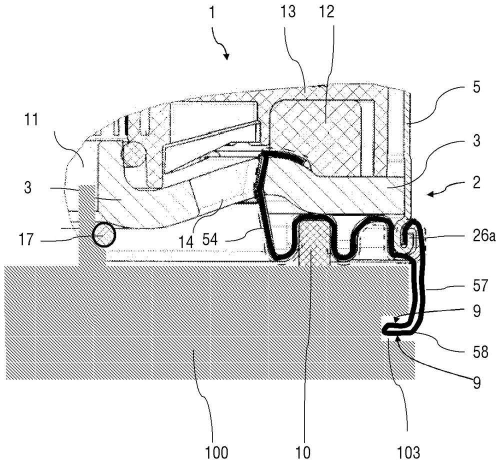
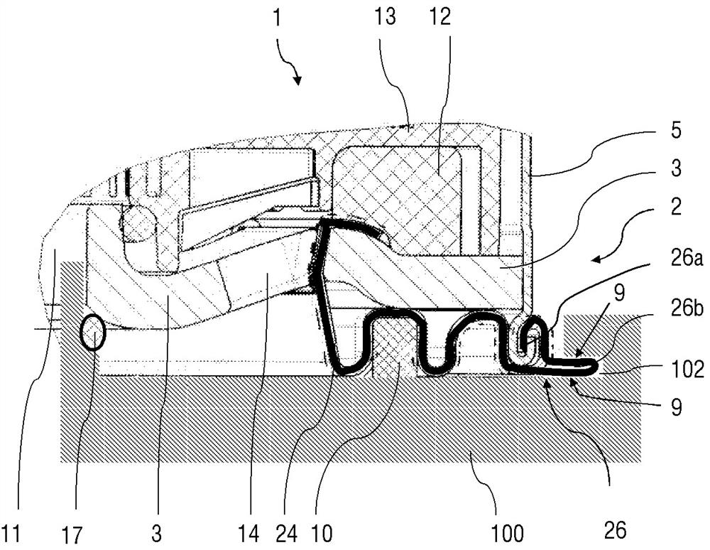
[0031] figure 1 A detailed view of a section of a desiccant cartridge according to an exemplary embodiment of the invention is shown here. figure 1 In particular, a section of the radially outer lower region of the desiccant cartridge 1 is shown. The interior of the desiccant cartridge 1 can be constructed in a manner known per se, for example as described in the laid-open documents DE 10 2013 103 066 A1, DE 10 2012 105 137 A1 and DE 10 2007 034 435 A1. For example, the reference numeral 12 designates an oil filter formed by a fleece and the reference numeral 13 designates an inner container for a desiccant, of which only a small part can be seen. figure 1 The vertical arrows in indicate the axial direction of the desiccant cylinder, and the horizontal arrows indicate the radial direction of the desiccant cylinder.

[0032] The cartridge housing of the desiccant cartridge has, in a manner ...


PUM


Abstract

The invention relates to a device for the detachable fastening of a desiccant cartridge on a housing of a compressed air production device of a vehicle, in particular a commercial vehicle. The device comprises a flange (6) with an abutment surface (9) at the bottom of the desiccant cartridge and an insertion opening (101) on the housing (100) of the compressed air production device, The flange ( 6 ) can be inserted at least in sections into the insertion opening ( 101 ) and in the insertion opening ( 101 ) the flange is connected in the axial direction by a form fit in the inserted state. stop.

Description

technical field [0001] The invention relates to a device for detachably fastening a desiccant cartridge on a housing of a compressed air production device of a vehicle, in particular a commercial vehicle. Background technique [0002] In particular, compressed air systems in commercial vehicles require so-called air preparation systems if they are connected downstream of the air compressor. In particular, the air is dried and filtered, and the oil components are separated off. These processes all take place in so-called desiccant cartridges, roughly speaking, consisting of a bottom plate with openings for the flow of air through and a cup-shaped or basin-shaped cover, the bottom plate and the The covers are fixedly connected to each other. Moisture-adsorbing granules are present therein, which draw moisture away from the air flowing through. Such pellets have only a limited service life when used in commercial vehicles. The reason for this is that the oil mist contained ...

Claims


Application Information

Patent Timeline
Patent Type & Authority Patents(China)
IPC IPC(8): F15B21/048B01D53/04B01D53/26B60T17/00
CPCB01D53/0407B01D53/261B60T17/004F15B21/041F15B21/048B01D2259/455B01D2257/80B01D53/26B60T17/00F15B21/04F16B2/241
Inventor O.考珀特W.科兰G.哈斯尔贝格T.霍夫斯泰特
Owner MAN TRUCK & BUS AG
Why Eureka
Try Eureka