Device and method for directly measuring photon polarization density matrix

A photon polarization and measuring device technology, which is applied in measuring devices, optical radiation measurement, measuring the polarization of light, etc., can solve the problem that quantum tomography cannot provide quantum physical coherence methods

Active Publication Date: 2017-08-04
黑龙江省工研院资产经营管理有限公司
View PDF6 Cites 5 Cited by
  • Summary
  • Abstract
  • Description
  • Claims
  • Application Information

AI Technical Summary

Problems solved by technology

[0003] The purpose of the present invention is to solve the problem that quantum tomography cannot directly obtain the coherence method in quantum physics, and to provide a direct measurement device and method for the photon polarization density of state matrix

Method used


Image

  • Device and method for directly measuring photon polarization density matrix
  • Device and method for directly measuring photon polarization density matrix
  • Device and method for directly measuring photon polarization density matrix

Examples


specific Embodiment approach 1

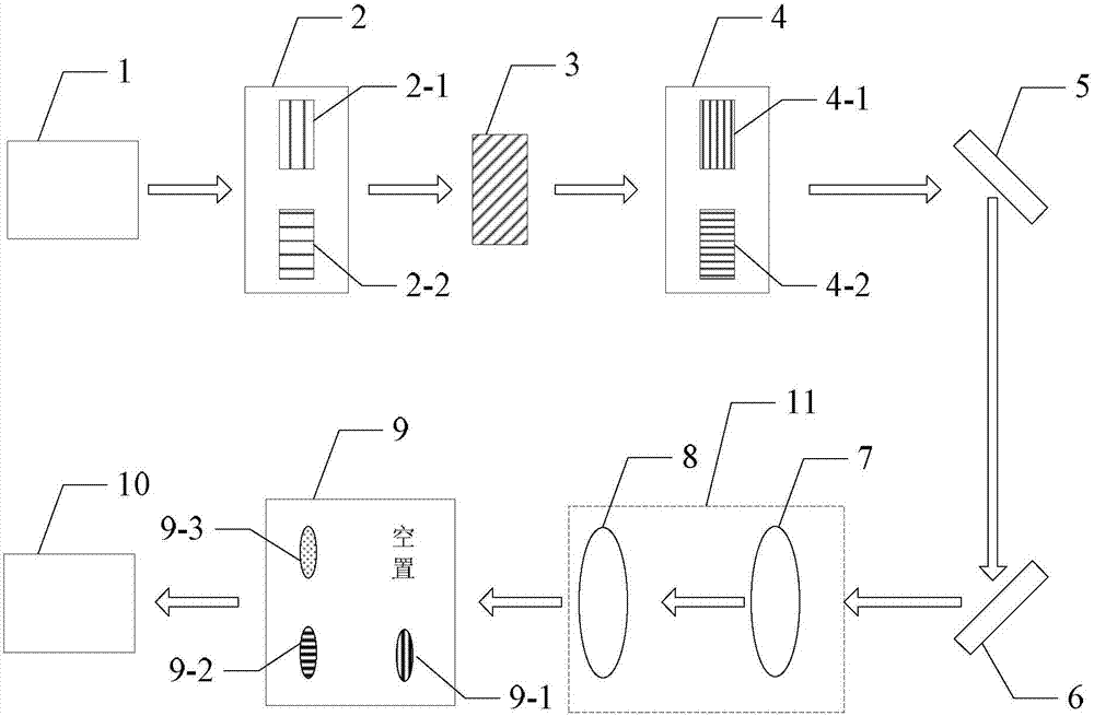
[0027] Specific implementation mode one: combine Figure 1 to Figure 3 Describe this embodiment mode, a kind of direct measurement device of photon polarization density of state matrix described in this embodiment mode, comprises the first state converter 2, the diagonal polarization dependent displacement crystal 3, the second state converter 4, the first convex lens 7. The second convex lens 8, the third state switch 9 and the CCD camera 10;

[0028] The signal to be measured is incident to the first state converter 2, the signal to be measured converted by the first state converter 2 is incident to the diagonal polarization dependent displacement crystal 3, and the signal to be measured converted by the diagonal polarization dependent displacement crystal 3 is incident to the second state converter 4, the signal to be measured converted by the second state converter 4 is incident on the imaging system 11, and the signal to be measured output by the imaging system 11 is inci...

specific Embodiment approach 2

[0075] Specific embodiment 2: This embodiment is to further limit the direct measurement device of a photon polarization density of state matrix described in specific embodiment 1. In this embodiment, it also includes a first mirror 5 and a second mirror 6 ;

[0076] Both the first mirror 5 and the second mirror 6 are arranged on the optical path between the second state switch 4 and the first convex lens 7 .

[0077] In this embodiment, the first reflective mirror 5 and the second reflective mirror 6 are added to assist the outgoing light emitted by the second state switch 4 to enter the first convex lens 7 .

specific Embodiment approach 3

[0078] Specific embodiment three: the measurement method based on the direct measurement device of a photon polarization density of state matrix described in specific embodiment one,

[0079] The measurement method includes the following steps:

[0080] Step 1, adjust the first state converter 2, add the first vertical polarization-related displacement crystal 2-1 to the optical path; adjust the second state converter 4, and add the second vertical polarization-dependent displacement crystal 4-1 to the optical path; adjust the second Three-state converter 9, respectively spherical Fourier transform lens 9-3, horizontal cylindrical Fourier transform lens 9-2 and vertical cylindrical Fourier transform lens 9-1 and vacant state add optical path, every time The CCD images collected by the CCD camera 10 are collected once; respectively, the CCD images collected by the CCD camera 10 are calculated four times to obtain the first photon polarization density of state array element;

...


PUM


Abstract

A device and a method for directly measuring a photon polarization density matrix relate to a technology for directly measuring a photon polarization density matrix, and are disclosed in order to solve the problem that the quantum tomography fails to provide a method for directly getting the coherence in quantum physics. A to-be-measured signal enters a first state converter. The to-be-measured signal after conversion by the first state converter enters a diagonal polarization dependent displacement crystal. The to-be-measured signal after conversion by the diagonal polarization dependent displacement crystal enters a second state converter. The to-be-measured signal after conversion by the second state converter enters an imaging system. The to-be-measured signal output by the imaging system enters a third state converter. The to-be-measured signal after conversion by the third state converter is received by a CCD camera. The beneficial effects are as follows: the measuring method only needs three times of measurement of two substrates to determine arbitrarily selected density matrix elements without considering the system dimension (d), and is a very attractive and effective method to replace the tomography to detect the potential mixed state locally.

Description

technical field [0001] The invention relates to a direct measurement technology of a photon polarization state density matrix. Background technique [0002] Quantum State Tomography (QST) is a standard method for measuring density matrices. In the QST framework, it is usually necessary to use a large number of pre-prepared samples of the same quantum state to perform a series of overcomplete measurements based on incompatible basis vectors; then, based on a certain reconstruction algorithm, the measurement algorithm is fitted to obtain the quantum state the expression. Although many work results have emerged to improve QST, the scalability of the experimental device and the complexity of the reconstruction algorithm make QST weak in the face of high-dimensional systems. In addition, because QST is a global reconstruction process. Therefore, it is impossible to provide a method to directly obtain the coherence that is very interesting in quantum physics, for example: it ca...

Claims


Application Information

Patent Timeline
Patent Type & Authority Applications(China)
IPC IPC(8): G01J4/00G01J11/00
CPCG01J4/00G01J11/00G01J4/04
Inventor 张子静岑龙柱赵远张建东李硕
Owner 黑龙江省工研院资产经营管理有限公司
Why Eureka
Try Eureka