

An anti-roll torsion bar shaft protection sleeve, an anti-roll torsion bar system and disassembly method
A technology of anti-roll torsion bars and protective sleeves, which is applied in the direction of the device for lateral relative movement between the underframe and the bogie, can solve the problems of high maintenance or replacement costs, low installation efficiency, and cumbersome installation steps, and achieve Simplify installation steps, improve installation efficiency, and improve service life
Active Publication Date: 2019-01-22
ZHUZHOU TIMES NEW MATERIALS TECH
View PDF6 Cites 0 Cited by
- Summary
- Abstract
- Description
- Claims
- Application Information
AI Technical Summary
Problems solved by technology
(1) When installing the anti-roll torsion bar system on the bogie, it is necessary to insert the protective sleeve from one end of the torsion bar shaft first, then assemble the torsion arm on the torsion bar shaft, and finally the anti-roll The roll torsion bar system is installed on the bogie, so the steps are cumbersome, which increases the installation time of the anti-roll torsion bar system and reduces the installation efficiency of the anti-roll torsion bar system;
(2) If the protective sleeve is an integral structure, it will cause problems when the protective sleeve needs to be disassembled for maintenance, because the torsion arm on the left or right side must be removed first when disassembling, and the torsion arm and the torsion bar shaft are Interference fit, the torsion arm must be destroyed during disassembly, which increases the difficulty of dismantling the anti-roll torsion bar system and increases the repair or replacement cost of the anti-roll torsion bar system
When the protective sleeve in the above-mentioned patent documents adopts a monolithic structure, the installation steps will be cumbersome, the installation efficiency will be low, the disassembly will be difficult, and the maintenance or replacement cost will be high.
In addition, it should be noted that although the above-mentioned patent document mentions that the protective sleeve adopts a split structure, the specific scheme of the split-type protective sleeve is not disclosed in this patent document. Therefore, it is necessary to go further. Research
Method used
View moreImage
Smart ImageViewing Examples

Examples
Embodiment
Login to View More PUM
 Abstract
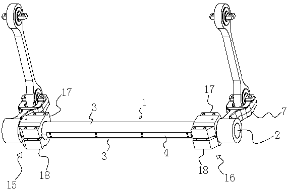
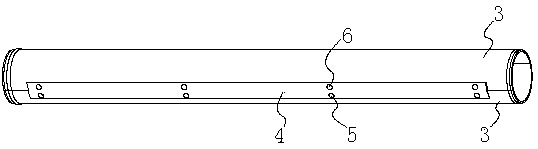
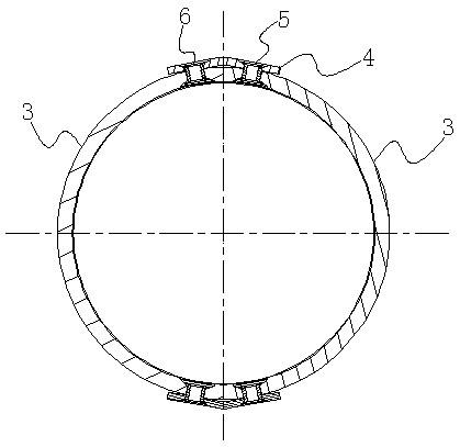
The invention discloses a side-rolling resistant torsion bar shaft protective sleeve, a side-rolling resistant torsion bar system and an assembling and disassembling method. The side-rolling resistant torsion bar shaft protective sleeve is of a split type structure and is divided into two or more protective shells in the axial direction of the sleeve, and the adjacent edges of the adjacent protective shells are connected through connecting parts to form a complete side-rolling resistant torsion bar shaft protective sleeve. The steps are simplified during assembling and disassembling of the side-rolling resistant torsion bar shaft protective sleeve, the efficiency is improved, the disassembling difficulty is lowered, and the maintaining or replacement cost is reduced.
Description
technical field The invention relates to a rail vehicle component and a disassembling method thereof, in particular to an anti-rolling torsion bar shaft protection sleeve, an anti-rolling torsion bar system and a disassembling method. Background technique The vibration of the vehicle mainly has six degrees of freedom: stretching vibration in the X direction, yaw vibration in the Y direction, ups and downs vibration in the Z direction, rolling vibration around the X axis, nodding vibration around the Y axis, and vibration around the Z axis. Shake your head and vibrate. The anti-roll torsion bar system mainly plays the role of adjusting the roll stiffness of the vehicle and controlling the roll vibration of the vehicle. The anti-roll torsion bar system is installed on the rail transit vehicle. When the vehicle is rolling, the torsion bar shaft is twisted and deformed, and together with other components, it provides the roll stiffness required for the safe operation of the veh...
Claims
Login to View More Application Information
Patent Timeline
 Patent Type & AuthorityPatents(China)
IPC IPC(8): B61F5/24
CPCB61F5/24
Inventor肖国柱刘文松罗斌王亚平庄征宇高发雄范湘
OwnerZHUZHOU TIMES NEW MATERIALS TECH