Buried rainwater shunting system

A diversion system, buried technology, applied in waterway systems, water supply devices, drainage structures, etc., can solve the problems of water resources waste, increased processing difficulty, high cost, etc.

Pending Publication Date: 2017-08-08
SUZHOU CHURUN ECOLOGICAL TECH
View PDF17 Cites 0 Cited by
  • Summary
  • Abstract
  • Description
  • Claims
  • Application Information

AI Technical Summary

Problems solved by technology

Among them, because there are not a lot of impurities, leaves and garbage in the rainwater from the eaves, it is generally used as a rainwater source for separate treatment, but the amount of this rainwater is small, and most of the rainwater is discharged from the rainwater well, which is an important discharge of a large amount of rainwater collection. land, but it has a lot of impurities, leaves and garbage, which has increased processing difficulty and high cost, which is not conducive to recycling, resulting in a great waste of water resources

Method used


Image

  • Buried rainwater shunting system
  • Buried rainwater shunting system
  • Buried rainwater shunting system

Examples


Embodiment 1

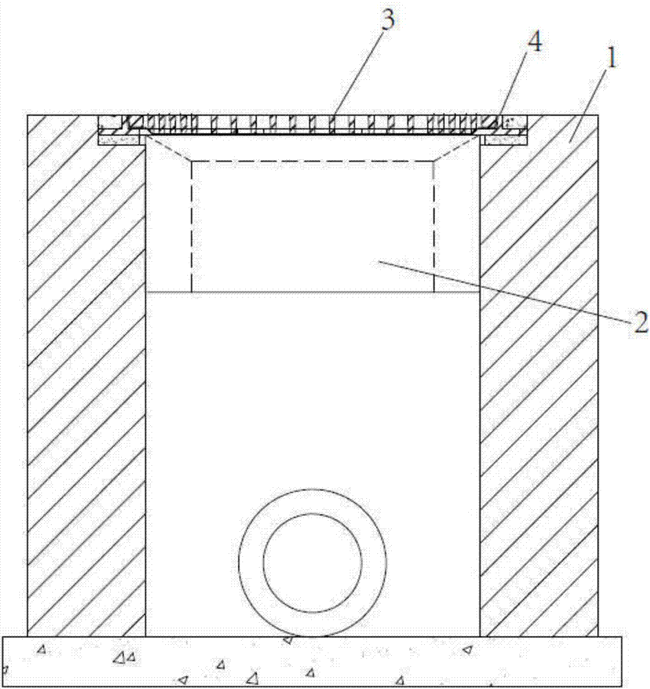
[0032] refer to figure 1 As shown, a buried rainwater distribution system,

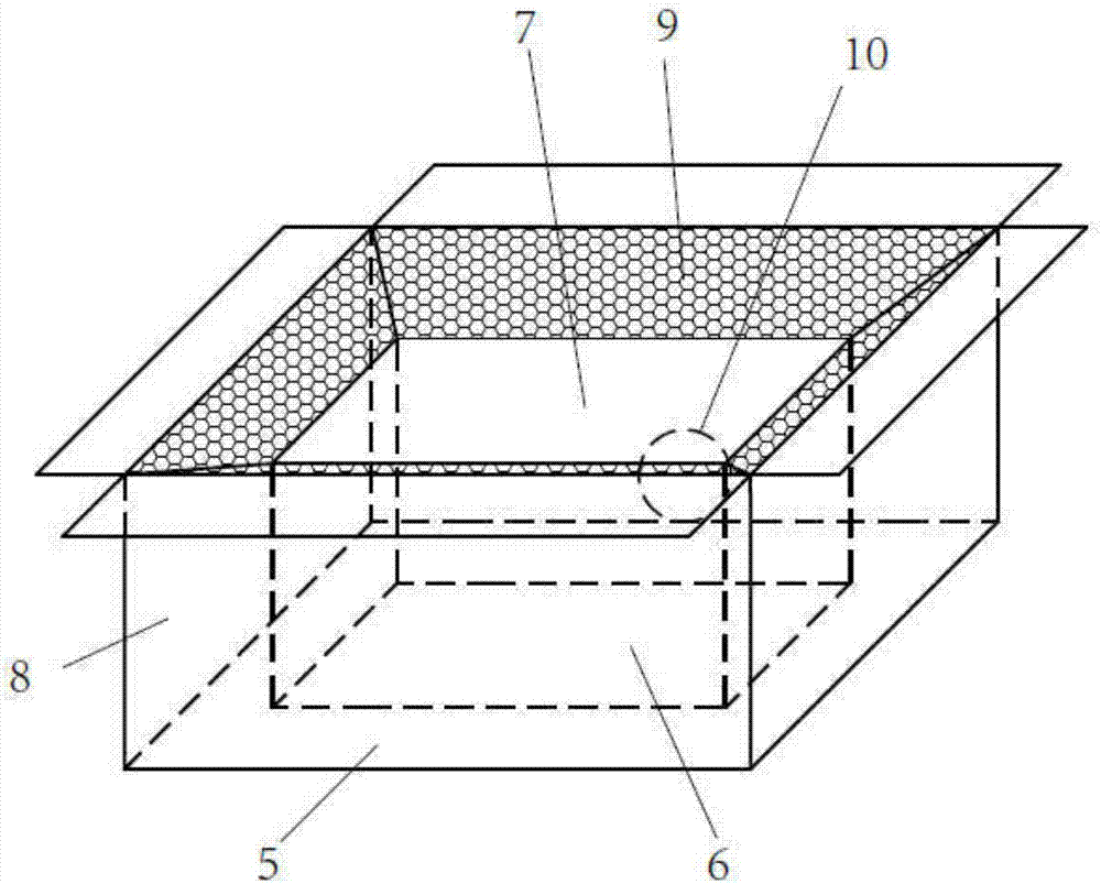
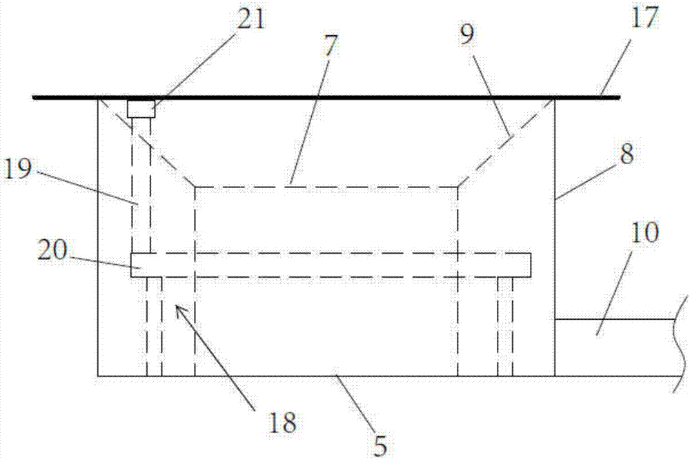
[0033] Well 1, a rainwater diversion device 2 is installed in the well, and a rainwater grate 3 is arranged above the rainwater diversion device. The rainwater grate is fixed on the top of the well through the well ring 4; The device can separate the impurity leaves from the rainwater. It collects the rainwater and discharges it. The impurity leaves flow into the well without affecting the original design and function of the well. It is also suitable for the installation of the existing well.

[0034] refer to Figure 5 to Figure 8 As shown, the rainwater grate includes a grate body 11, the grate body is provided with a first mesh area 12, the first mesh area includes a number of evenly arranged first rainwater slits 13, and the periphery of the first mesh area is located in the water inlet direction. The grate body is also provided with a second mesh area 14, the first mesh area includes a number o...

Embodiment 2

[0043] The difference between Embodiment 2 and Embodiment 1 is that the second rainwater passage slit is arranged on both sides of the first mesh area, which only needs to be arranged on the side where the rainwater enters. In the figure, it is designed when there is rainwater on both sides. The body of the grate can also play a drainage role.

Embodiment 3

[0045] The difference between Embodiment 3 and Embodiment 1 is that the width of the second rainwater slit is 5mm, the height of the spoiler protrusion is 2mm, the second rainwater slit width is small, and the possibility of impurities entering is even smaller, making the filtering effect Improvement, the spoiler protrusions block to ensure that rainwater will not directly flow through the second rainwater slit with a small diameter, thereby reducing the inflow of rainwater.


PUM

PropertyMeasurementUnit
Rotation angleaaaaaaaaaa

Abstract

The invention discloses a buried rainwater shunting system which comprises a shaft way, wherein a rainwater shunting device is arranged in the shaft way; a rainwater perforated strainer is arranged above the rainwater shunting device; the rainwater perforated strainer is fixedly arranged at the top of the shaft way through a well loop; the rainwater shunting device comprises a base plate; a passageway opening is formed in the middle of the base plate; a first fence is arranged on the peripheral edge of the passageway opening; a second fence is arranged on the peripheral edge of the base plate; a separation plate is arranged between the top of the first fence and the top of the second fence; a drainage pipeline is further arranged at the periphery of the second fence; the rainwater perforated strainer comprises a perforated strainer body; a plurality of first rainwater gaps are formed in the perforated strainer body; a plurality of second rainwater gaps are formed in the peripheral edges of the first rainwater gaps; the width of each second rainwater gap is less than that of each first rainwater gap; and flow turbulence bulges are further arranged on the surface of the perforated strainer body on one side, which is located in a first mesh region, of the second rainwater gaps. The buried rainwater shunting system can effectively separate rainwater and reduce the rainwater treatment difficulty and cost and is high in recycling efficiency.

Description

technical field [0001] The invention relates to the field of rainwater treatment, in particular to an underground rainwater diversion system. Background technique [0002] Rainwater treatment is the purification process of surface runoff water (rainwater, snowmelt water, sprinkler water) in urban areas. According to different pipeline system drainage systems, rainwater treatment can be treated alone or combined with domestic sewage and industrial wastewater. Among them, because there are not a lot of impurities, leaves and garbage in the rainwater from the eaves, it is generally used as a rainwater source for separate treatment, but the amount of this rainwater is small, and most of the rainwater is discharged from the rainwater well, which is an important discharge of a large amount of rainwater collection. However, it has a large amount of impurities, leaves and garbage, which has increased processing difficulty and high cost, which is not conducive to recycling, resultin...

Claims


Application Information

Patent Timeline
IPC IPC(8): E03F5/04E03F5/06E03F5/14E03F9/00
CPCE03F5/0401E03F5/0402E03F5/0404E03F5/06E03F2005/061E03F2201/10
Inventor 廖述成李晨榴
Owner SUZHOU CHURUN ECOLOGICAL TECH
Why Eureka
Try Eureka