
Connecting part of combined structure of steel and concrete and combining beam consisting of same

A technology of combining structures and connectors, which is applied in the direction of load-bearing elongated structural components, structural elements, building components, etc., can solve the problems of low construction efficiency, increase the difficulty and workload of construction, and improve construction efficiency. , Save operating time, high shearing effect

Inactive Publication Date: 2017-08-08
SICHUAN UNIV
View PDF6 Cites 8 Cited by
  • Summary
  • Abstract
  • Description
  • Claims
  • Application Information

AI Technical Summary

Problems solved by technology

However, the openings of the existing open-hole steel plate connectors are closed, which often increases the difficulty and workload of construction when arranging through steel bars, and the construction efficiency is low

Method used


Image

  • Connecting part of combined structure of steel and concrete and combining beam consisting of same
  • Connecting part of combined structure of steel and concrete and combining beam consisting of same
  • Connecting part of combined structure of steel and concrete and combining beam consisting of same

Examples


Embodiment 1

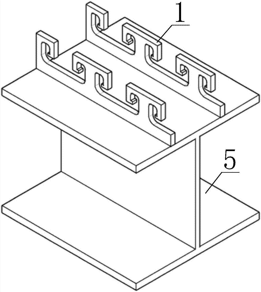
[0027] Such as figure 1 As shown, a steel and concrete composite structure connector includes a bottom plate 101 and a steel bar positioning mechanism, wherein the steel bar positioning mechanism includes a web 102, a flange plate 103 and a steel bar support block 104, and the bottom plate 101 of this embodiment is set horizontally , the web 102 is arranged vertically and its lower end is fixed on the upper surface of the bottom plate 101 , and the flange plate 103 is arranged above the bottom plate 101 and parallel to the bottom plate 101 . One end of the flange plate 103 of this embodiment is fixedly connected to the side wall of the web 102, and the bottom of the flange plate 103 is formed with a positioning gap. A rebar embedding opening is formed between the other end of the support block 104 and the side wall of the positioning notch. In this embodiment, the area between the steel bar support block 104 and the bottom plate 101 is the first steel bar rest area, and the a...

Embodiment 2

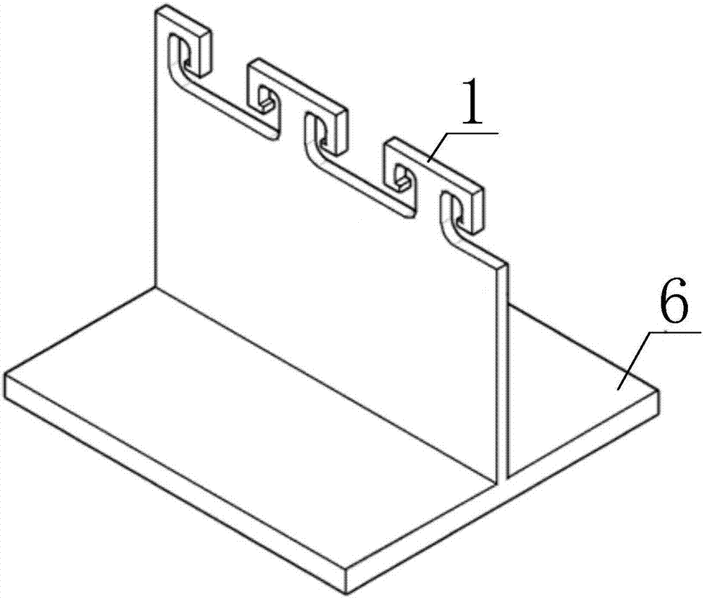
[0039] The difference between this embodiment and embodiment 1 is that this embodiment provides another kind of composite beam, the structure of the composite beam of this embodiment is as follows: this embodiment also includes T-shaped steel beam 6, upper horizontal reinforcement 2, lower horizontal reinforcement 3 and the concrete slab 4, wherein the connecting piece 1 is fixed on the T-shaped steel web of the T-shaped steel beam 6, the upper layer of transverse reinforcement 2 passes through the second steel bar resting area of ​​the connecting piece 1 and is supported by a steel bar support block 104, and the lower layer The transverse reinforcement 3 passes through the first reinforcement rest area of ​​the connector 1 and is supported by the bottom plate 101 ; the concrete slab 4 wraps the connector 1 , the upper transverse reinforcement 2 and the lower transverse reinforcement 3 . When this embodiment is specifically set up, the number of T-shaped steel beams 6 is more t...


PUM


Abstract

The invention discloses a connecting part of a combined structure of steel and concrete. The connecting part comprises a bottom plate and reinforced steel positioning mechanisms, wherein the reinforced steel positioning mechanisms comprise webs, flange plates and reinforcing steel support blocks; the bottom plate is horizontally arranged; the webs are arranged vertically; the lower ends of the webs are fixed on the upper end surface of the bottom plate; the flange plates are arranged above the bottom plate and are parallel to the bottom plate; one end of each flange plate is fixedly connected to a side wall of each web; positioning notches are formed in the bottoms of the flange plates; the reinforcing steel support blocks are embedded into the positioning notches; one end of each reinforcing steel support block is fixedly connected with each flange plate; reinforcing steel embedding holes are formed between the other ends of the reinforcing steel support blocks and the side walls of the positioning notches; areas between the reinforcing steel support blocks and the bottom plate are first reinforcing steel holding areas; areas inside the positioning notches above the reinforcing steel support blocks are second reinforcing steel holding areas. The invention further discloses a combining beam consisting of the connecting part. By adopting the connecting part, reinforcing steel can be conveniently connected in lap joint, and the construction efficiency can be improved.

Description

technical field [0001] The invention relates to the field of steel-concrete composite structures, in particular to a steel-concrete composite structure connector and a composite beam formed therefrom. Background technique [0002] Steel and concrete composite structure is a performance-optimized structural form developed based on steel structure and concrete structure. Through reasonable design, this structural form can give full play to the material properties of steel in tension and concrete in compression, so as to obtain significant Economic benefits, so it is increasingly widely used in engineering. [0003] The connection between the steel and concrete components is the key to ensure that the two can work together, and can effectively prevent the relative slippage and separation between the steel beam and the concrete panel. For a long time, in order to find a reliable way to make steel and concrete work together, researchers have conducted a lot of experiments and re...

Claims


Application Information

Patent Timeline
IPC IPC(8): E04C3/293E04C3/02
CPCE04C3/02E04C3/293
Inventor 王清远薛辉王志宇
Owner SICHUAN UNIV
Learn More