
Energy filtering device and energy collecting device

A technology of energy filtration and energy collection, applied in machines/engines, non-displacement pumps, mechanical equipment, etc., can solve the problems of obstructing gas flow and reducing the utilization efficiency of pressurized gas, achieving low transportation resistance, high utilization efficiency, The effect of easy transportation

Inactive Publication Date: 2017-08-08
河北熵航能源科技有限公司
View PDF8 Cites 0 Cited by
  • Summary
  • Abstract
  • Description
  • Claims
  • Application Information

AI Technical Summary

Problems solved by technology

[0004] However, the pressurized gas generated by the above-mentioned gas supply device contains a large amount of liquid. During the transportation of the pressurized gas, these liquids will seriously hinder the flow of the gas, thereby greatly reducing the utilization efficiency of the pressurized gas.

Method used


Image

  • Energy filtering device and energy collecting device
  • Energy filtering device and energy collecting device
  • Energy filtering device and energy collecting device

Examples


Embodiment Construction

[0024] In order to understand the technical solution of the present invention more clearly, the present invention will be described in detail below in conjunction with the accompanying drawings. The embodiments of the present invention have exemplary functions, and insubstantial improvements made by those skilled in the art based on the embodiments of the present invention shall fall within the protection scope of the present invention.

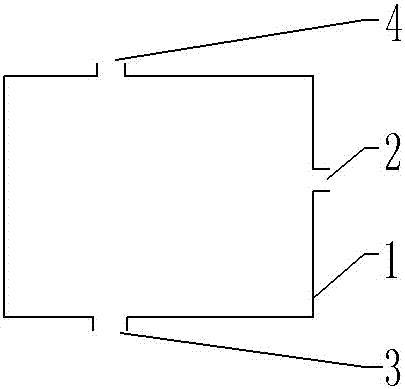
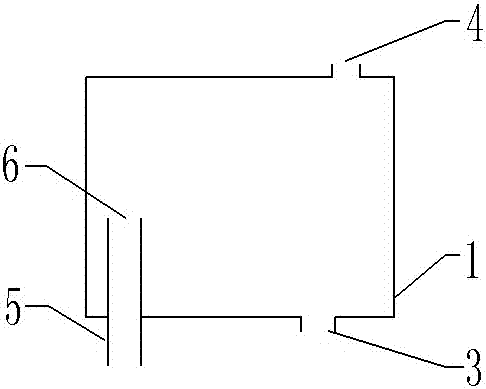
[0025] Such as figure 1 The shown energy filtering device includes a filter chamber 1 , the filter chamber 1 includes an air inlet 2 , a water outlet 3 and an air outlet 4 , and the water outlet 3 is located on the lower side of the air outlet 4 .

[0026] The structure of the filter chamber can be a cube, a cuboid, a cylinder, a sphere or a cone, etc.; according to different needs, other structures can also be added to the filter chamber; the material of the filter chamber is plastic, ceramics, stainless steel or other metal materials .

...


PUM


Abstract

The invention belongs to the technical field of hydraulic energy utilization, and particularly relates to an energy filtering device and an energy collecting device. The energy filtering device comprises a filtering bin. The filtering bin comprises an air inlet, a water outlet and an air outlet. The water outlet is located in the lower side of the air outlet. The energy filtering device can be used for pressure gas filtering, and energy losses in the transporting process can be reduced when no liquid resistance or small liquid resistance acts on the pressure gas.

Description

technical field [0001] The invention belongs to the technical field of hydraulic energy utilization, and in particular relates to an energy filtering device and an energy collecting device. Background technique [0002] The pump is mainly used to transport liquids such as water, oil, acid-base liquid, emulsion, suspoemulsion and liquid metal, and can also transport liquid and liquid containing suspended solids. The application number is 201010278745.6, and the patent titled "Gas-Liquid Pump" discloses a gas-liquid pump. The pump is composed of a liquid pipe and a gas pipe. The energy source of the gas-liquid pump is pressurized gas, which will not cause pollution to the environment, and can save a lot of electric energy, petroleum energy and the like. [0003] In order to provide pressurized gas, the above-mentioned patent also discloses a gas supply device, which mixes the gas near the intake into the liquid through the flowing liquid, and separates the gas into small bubb...

Claims


Application Information

Patent Timeline
Patent Type & Authority Applications(China)
IPC IPC(8): F04F1/00
CPCF04F1/00
Inventor 翟爱民
Owner 河北熵航能源科技有限公司
Learn More