Rapid microfluidic mixer based on coplanar coil group

A coil set, microfluidic technology, applied in mixers, chemical instruments and methods, dissolution and other directions, can solve the problems of unimplemented, limited application scope, complex production process, etc., to accelerate the stirring and mixing process and facilitate quality control. , the overall compact effect

Inactive Publication Date: 2017-08-11
HUAZHONG UNIV OF SCI & TECH
View PDF4 Cites 8 Cited by
  • Summary
  • Abstract
  • Description
  • Claims
  • Application Information

AI Technical Summary

Problems solved by technology

At present, the microfluidic mixing system is generally divided into two types: static type and dynamic type. The former relies on the interdiffusion of the liquid itself. This method requires a long reaction time and is difficult to meet the requirements of rapid mixing; the latter is through External force accelerates the flow of microfluids. Existing studies include electromagnetic-driven, thermal-driven, ultrasonic-driven, etc. Because of its relatively faster overall mixing speed, laboratory research on dynamic types has made great progress in recent years. progress, but has not been put into practical application fields, the important reason is that the process is complex or the application field is relatively narrow
[0003] Specifically, for example, Liang-Hsuan Lu et al. have developed an arrayed micromotor using MEMS technology, which can rotate at high speed under external magnetic drive to achieve microfluidic mixing, but its manufacturing process is complicated and difficult to achieve Large-scale promotion; Evan uses water vapor generated at high temperature to flow back and forth in multiple circulation chambers, so that the fluid molecules are chaotic and fully mixed, but this method is not suitable for liquids whose properties are affected by heat, so its application range is limited. In addition, H.Monnier et al. used acoustic cavitation to generate turbulent flow. The domestic Zhen Yang based on focused ultrasonic waves can disturb the flow field to generate small vortices, thus using PZT to generate vibrating ultrasonic waves and focus on the flow field. In order to improve the mixing effect, however, this method can only cause better mixing in a small range, so it is difficult to achieve a sufficient mixing effect in practice.

Method used


Image

  • Rapid microfluidic mixer based on coplanar coil group

Examples


Embodiment Construction

[0023] In order to make the object, technical solution and advantages of the present invention clearer, the present invention will be further described in detail below in conjunction with the accompanying drawings and embodiments. It should be understood that the specific embodiments described here are only used to explain the present invention, not to limit the present invention. In addition, the technical features involved in the various embodiments of the present invention described below can be combined with each other as long as they do not constitute a conflict with each other.

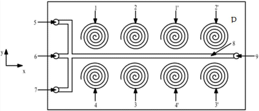
[0024] figure 1 It is a schematic diagram of the overall structure of the microfluidic fast mixer shown exemplary according to the present invention, such as figure 1 As shown in , the microfluidic fast mixer only needs to include a first inlet 6, a second inlet 5, a third inlet 7, an outlet 9, a mixing channel 8 and a plurality of coil unit units (two coils are exemplarily shown in the figure ...


PUM


Abstract

The invention belongs to the related field of microfluidic equipment and discloses a rapid microfluidic mixer based on a coplanar coil group. The mixer comprises a mixing channel, multiple inlets and outlets arranged on two opposite sides of the mixing channel as well as multiple coil group units sequentially arranged in the axis direction of the mixing channel and located in the same plane, wherein the multiple inlets are used for guiding different fluids and magnetic nanoparticles which are to be mixed, each coil group unit consists of four coils which are symmetrically arranged above and below the axis of the mixing channel, alternating currents which have identical frequency and amplitude and whose phases sequentially have 90-degree difference pass through the four coils, thus, rotating magnetic fields are generated continuously along the mixing channel to drive the nanoparticles to rotate, and the stirring and mixing process is accelerated. Tests indicate that compared with the prior art, the mixer has the advantages that the mixing process can be accelerated significantly and the high-quality fluid mixing effect can be obtained at a longer distance and in a wider range.

Description

technical field [0001] The present invention belongs to the related field of microfluidic equipment, and more specifically relates to a microfluidic fast mixer based on a coplanar coil group, which can form multiple rotating magnetic field domains along the axial direction of the mixing channel, and make the fluid obtain Efficient, high-quality, and extended mixing effects. Background technique [0002] The mixing of micro-fluids is an important step to achieve clinical biochemical reactions. Due to the strict requirements on the composition and quality of trace elements, the liquid in many micro-biochemical analyzes of quantitative analysis needs to be controlled in microliters and nanoliters. The traditional mixing method has been difficult to meet this requirement. Research on micro-hybrid systems has made great progress as a new field. At present, the microfluidic mixing system is generally divided into two types: static type and dynamic type. The former relies on the ...

Claims


Application Information

Patent Timeline
Patent Type & Authority Applications(China)
IPC IPC(8): B01F13/00
CPCB01F33/3032B01F2101/23
Inventor 李千刘晓军章明卢珍
Owner HUAZHONG UNIV OF SCI & TECH
Why Eureka
Try Eureka