
Welding process of bimetal mechanical composite pipe

A welding process and composite pipe technology, applied in metal processing equipment, welding equipment, manufacturing tools, etc., can solve the problems of high welding cost, easy to produce brittle hard tissue, and large stress concentration at the welding toe, so as to reduce welding cost and Welding time, reducing stress concentration, and reducing the effect of welded joint cracks

Inactive Publication Date: 2020-01-14
CHINA UNIV OF PETROLEUM (EAST CHINA)
View PDF6 Cites 0 Cited by
  • Summary
  • Abstract
  • Description
  • Claims
  • Application Information

AI Technical Summary

Problems solved by technology

[0004] The purpose of the present invention is to provide a welding process for bimetal mechanical composite pipes, which is used to solve the shortcomings of the existing welding process, such as large stress concentration at the welding toe, easy to produce brittle hard structures, and high welding costs, so as to improve welding efficiency and ensure welding quality

Method used


Image

  • Welding process of bimetal mechanical composite pipe
  • Welding process of bimetal mechanical composite pipe
  • Welding process of bimetal mechanical composite pipe

Examples


Embodiment example 1

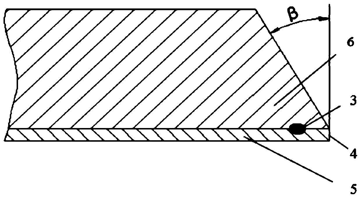
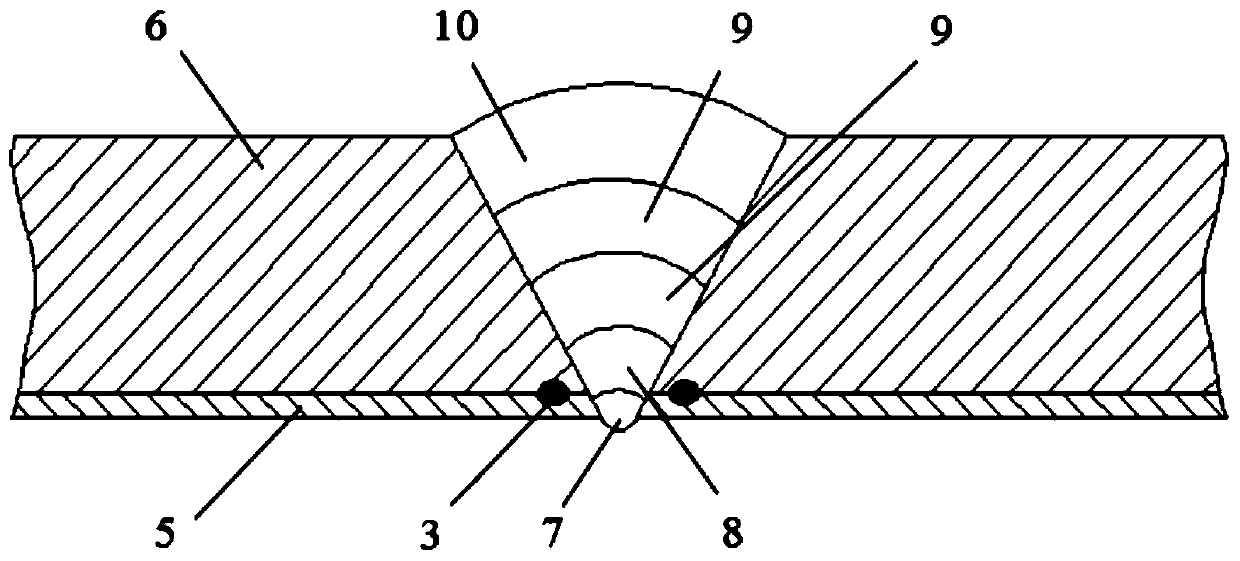
[0024] In this embodiment, the welded mechanical composite pipe 1 is composed of a stainless steel liner pipe 5 made of 316 stainless steel and a carbon steel base pipe 6 made of L415 carbon steel, and its specification is Φ355×(11+2) mm.

[0025] Step 1. Use resistance spot welding to spot weld the inner lining layer and the base layer at the pipe end, and then process the groove. The processing process is as follows:

[0026] 101. Adjust the matching position of the mechanical composite tube and the electrode of the spot welding machine so that the axis of the mechanical composite tube 1 is on the same surface as the electrode 2 of the spot welding machine, and the two electrodes of the spot welding machine are respectively located inside and outside the tube, and the electrode axis The distance from the heart to the pipe end is 15mm, see figure 1 ;

[0027] 102. Use a spot welding machine to spot weld the mechanical composite pipe. The diameter of the spot welding electro...

Embodiment example 2

[0037] In this embodiment, the welded mechanical composite pipe 2 is composed of a stainless steel lining pipe 6 made of 316 stainless steel and a carbon steel base pipe 5 made of 20G carbon steel, and its specification is Φ76x (7+2)mm . The difference from implementation case 1 is:

[0038] In step 101, when the spot welder spot welds, the distance between the axis of the electrode and the pipe end is 10mm; in step 102, the spot welder is used to spot weld the mechanical composite pipe, the electrode pressure is 8kN, the spot welding current is 25kA, and the mechanical composite pipe rotates The angle is 30°.

[0039] The welding wire used in the bottom welding in step 2 is ER316L, the welding current is 70A, and the flow rate of argon gas is 9L / min. The welding wire ER316L contains the following chemical components: 0.02%C, 1.85%Mn, 0.34% by weight Si, 0.001% S, 0.015% P, 18.73% Cr, 12.50% Ni and 2.36% Mo.

[0040]The welding wire used in transition welding in step 3 is E...


PUM


Abstract

The invention discloses a resistance spot-welding technique for the end of a bimetal mechanical composite pipe. The resistance spot-welding technique for the end of the bimetal mechanical composite pipe comprises the following steps of (1) treatment of a welding groove, specifically, the treatment process comprises the sub-steps that the mechanical composite pipe is adjusted to the proper position so as to be suitable for welding through a resistance spot-welding machine, and spot welding starts to be conducted; after each spot is spot-welded, the mechanical composite pipe is made to rotate by 10-30 degrees by adjusting tool equipment, and spot welding is conducted again till the mechanical composite pipe rotates by 360 degrees; and the spot-welded mechanical composite pipe is machined into a V-shaped groove with a blunt edge; (2) back welding, specifically, the mechanical composite pipes are assembled through an aligning device; (3) transition welding; and (4) filling cosmetic welding. By adoption of the resistance spot-welding technique for the end of the bimetal mechanical composite pipe, relative sliding between a base layer and a lining layer of the mechanical composite pipe can be avoided, stress concentration of a weld joint can be lowered, and the number of generated weld cracks is reduced; and meanwhile, while the welding quality is guaranteed, the welding time can be greatly shortened, and the welding cost is reduced.

Description

technical field [0001] The invention belongs to the field of metal welding of pipeline pressure vessels, and in particular relates to a welding process of bimetallic mechanical composite pipes. Background technique [0002] With the increasing demand for energy from economic development, oil and gas field development and oil and gas storage and transportation have put forward higher requirements for anti-corrosion technology and pipeline materials. It is difficult to take into account the aspects of corrosion resistance, strength and economy for single-component pipes, which leads to the emergence of bimetallic composite pipes. Bimetal composite pipes are divided into metallurgical composite pipes and mechanical composite pipes according to the different bonding methods. Among them, mechanical composite pipes are widely used in today's society because of their simple production, low price and good comprehensive performance. However, the application of bimetallic mechanical ...

Claims


Application Information

Patent Timeline
Patent Type & Authority Patents(China)
IPC IPC(8): B23K11/11
CPCB23K11/11
Inventor 韩彬韩浩李立英王勇韩国良
Owner CHINA UNIV OF PETROLEUM (EAST CHINA)
Learn More