
Automatic welding machine and automatic welding method thereof

An automatic welding machine and welding parts technology, applied in welding equipment, auxiliary welding equipment, welding/cutting auxiliary equipment, etc., can solve the problems of inability to ensure welding deformation, high welding cost of manipulators, and inability to ensure high efficiency, etc., to improve welding efficiency, reducing welding costs, and ensuring the effect of deformation

Active Publication Date: 2015-06-10
无锡乔尼威尔铁路设备科技有限公司
View PDF8 Cites 17 Cited by
  • Summary
  • Abstract
  • Description
  • Claims
  • Application Information

AI Technical Summary

Problems solved by technology

The external structure of the shock absorber is called the oil storage cylinder and the dust cover. This part is a welded assembly, which is an extremely critical part of the shock absorber and a safety component. It requires extremely high reliability. The welding of the oil cylinder and the dust cover has always been carried out according to European standards, which has brought technical barriers to domestic manufacturers. Due to the various types and structures of shock absorbers, manual welding or pure robot welding is often used at home and abroad, but in manual welding, it is impossible to ensure The quality can be 100% qualified, but pure manipulator welding cannot guarantee high efficiency, and single manipulator welding cannot guarantee welding deformation, and the welding cost of multiple manipulators at the same time is relatively high

Method used


Image

  • Automatic welding machine and automatic welding method thereof
  • Automatic welding machine and automatic welding method thereof
  • Automatic welding machine and automatic welding method thereof

Examples


Embodiment Construction

[0029] The present invention is described in further detail now in conjunction with accompanying drawing. These drawings are all simplified schematic diagrams, and only illustrate the basic structure of the present invention in a schematic manner, so they only show the configurations related to the present invention.

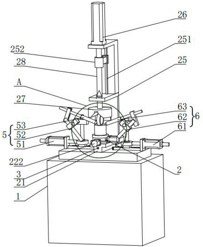
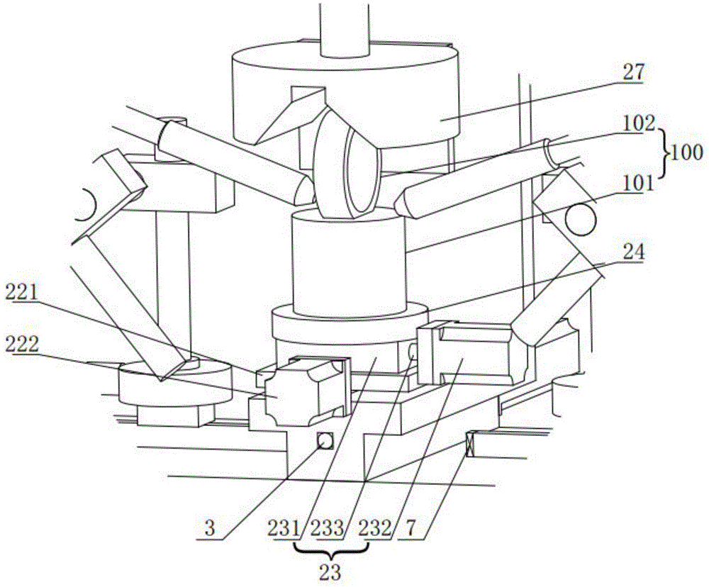
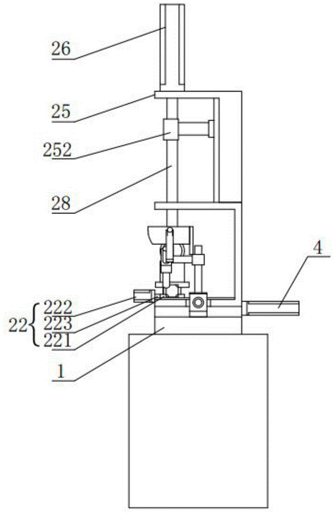
[0030] Such as figure 1 , figure 2 and image 3 As shown, an automatic welding machine according to the present invention includes a base 1, a fixture device 2, a first ball screw 3, a first servo motor 4, a first welding torch assembly 5, a second welding torch assembly 6 and a controller (not shown).

[0031] The fixture device 2 is installed on the base 1, and the fixture device 2 includes a first base 21, an X-axis positioning assembly 22, a Y-axis positioning assembly 23, a positioning fixture 24, a bracket 25, a third cylinder 26 and a clamping Fixture27. The first base 21 is installed on the base 1 , and the first ball screw 3 is installed in the fi...


PUM


Abstract

The invention relates to an automatic welding machine which comprises a base station, a clamp device, a first ball screw, a first servo motor, a first welding gun component and a second welding gun component. The clamp device is mounted on the base station, the first ball screw is penetratingly mounted in the clamp device and connected with the first servo motor which is fixedly mounted on the base station, the first servo motor drives the first ball screw to drive the clamp device to be in linear motion on the base station, the first welding gun component and the second welding gun component are positioned on two sides of the clamp device respectively, a first cylinder drives a first welding gun rack to adjust position of a first welding gun, and a second cylinder drives a second welding gun rack to adjust position of a second welding gun. The automatic welding machine has the advantages that welding needs on oil storage cylinders and dustproof covers of dampers diverse in structure can be met; the automatic welding machine can replace manual welding, so that welding efficiency is improved; the automatic welding machine can replace welding of a manipulator, so that welding quality is guaranteed while welding cost is lowered.

Description

technical field [0001] The invention belongs to the field of welding equipment, and in particular relates to an automatic welding machine. Background technique [0002] The train hydraulic shock absorber is a key component of train vibration reduction. At present, most of the main train hydraulic shock absorbers in my country are still based on foreign technology and brands. The external structure of the shock absorber is called the oil storage cylinder and the dust cover. This part is a welded assembly, which is an extremely critical part of the shock absorber and a safety component. It requires extremely high reliability. The welding of the oil cylinder and the dust cover has always been carried out according to European standards, which has brought technical barriers to domestic manufacturers. Due to the various types and structures of shock absorbers, manual welding or pure robot welding is often used at home and abroad, but in manual welding, it is impossible to ensure ...

Claims


Application Information

Patent Timeline
IPC IPC(8): B23K37/02B23K37/04
CPCB23K37/0247B23K37/04
Inventor 林乔宇
Owner 无锡乔尼威尔铁路设备科技有限公司
Learn More