
Plasma-arc welding device implemented by aid of TIG (tungsten inert gas) welding method

A plasma arc and welding method technology, which is applied in the field of plasma arc welding devices, can solve problems such as unfavorable manual operation, high equipment cost, and complex structure, so as to improve welding efficiency and weld quality, reduce welding cost, and expand the scope of application Effect

Active Publication Date: 2015-06-03
SHENYANG JINCHANG LANYU NEW MATERIAL CO LTD
View PDF6 Cites 17 Cited by
  • Summary
  • Abstract
  • Description
  • Claims
  • Application Information

AI Technical Summary

Problems solved by technology

However, because the equipment cost of the plasma welding machine is much higher than that of the TIG welding machine with the same electric power, the one-time investment of the equipment is large; because the structure of the traditional plasma welding torch is complex and heavy, it is not conducive to manual operation
The above two reasons limit the industrial application of plasma arc welding technology
[0004] To sum up, the existing TIG welding technology has low welding efficiency, while the traditional plasma arc welding technology improves the welding productivity, but the welding cost is high, and the welding device is relatively heavy. If the existing TIG welding torch can be modified to realize plasma Arc welding can not only improve the welding efficiency of TIG welding, but also significantly reduce the production cost of plasma arc welding method, and can also enhance the flexibility of plasma arc welding, so it has great application value

Method used

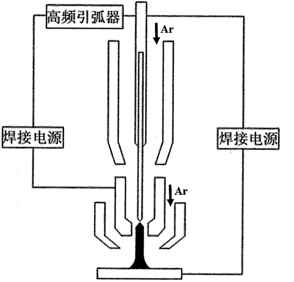

Image

  • Plasma-arc welding device implemented by aid of TIG (tungsten inert gas) welding method
  • Plasma-arc welding device implemented by aid of TIG (tungsten inert gas) welding method
  • Plasma-arc welding device implemented by aid of TIG (tungsten inert gas) welding method

Examples


Embodiment 1

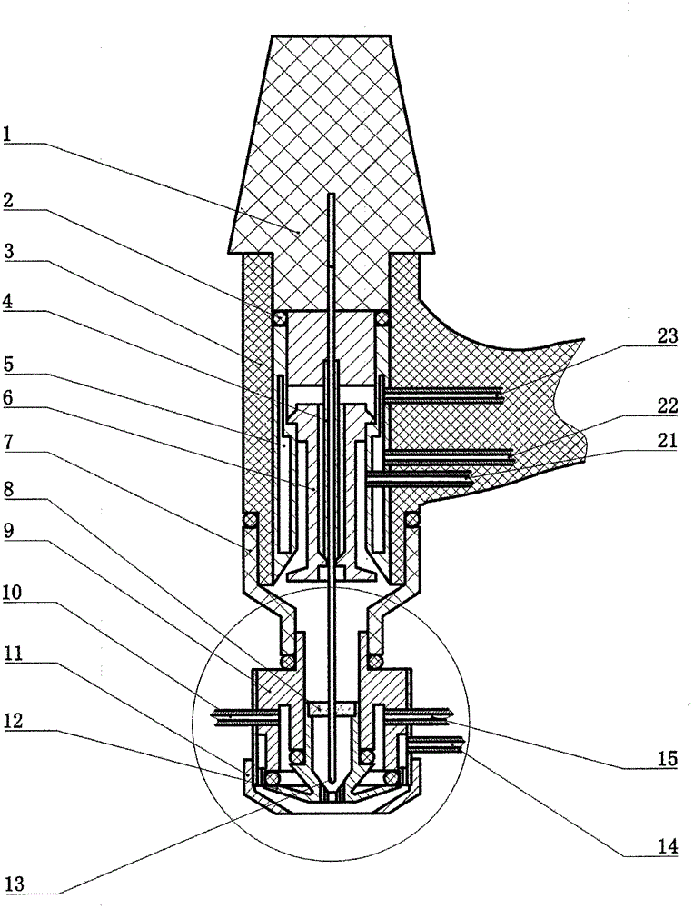
[0024] Such as figure 1 As shown, a device using TIG welding method to realize plasma arc welding, including electrode cap 1, sealing ring 2, upper gun body 3, tungsten pole clamp 4, flow guide 6, upper nozzle 7, centering ring 8, lower gun Body 9, lower water outlet pipe 10, protective cover 11, lower nozzle 12, tungsten pole 13, lower air inlet pipe 14, lower water inlet pipe 15, upper air inlet pipe 21, upper water inlet pipe 22 and upper water outlet pipe 23; electrode cap 1 and upper gun body 3 are connected by thread pairs, and the sealing ring 2 is located between the electrode cap 1 and the upper gun body 3. There is a water cooling groove 5 in the wall of the upper gun body 3, and the center of the electrode cap 1 is respectively opened with the same outer diameter as the tungsten electrode 13. The channel and the same channel as the outer diameter of the tungsten pole clip 4; the upper air inlet pipe 21, the upper water inlet pipe 22 and the upper water outlet pipe 2...

Embodiment 2

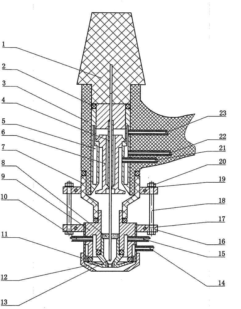
[0027] Such as image 3 As shown, the structure of this welding torch is the same as that in Embodiment 1, the difference is that the upper nozzle 7 and the outer wall of the lower torch body 9 are respectively covered with a clamp 16, which is realized by screw holes 17, bolts 18, spring washers 19 and nuts 20. The fastening and connection of the upper nozzle 7 and the lower gun body 9.


PUM


Abstract

The invention relates to a plasma-arc welding device implemented by the aid of a TIG (tungsten inert gas) welding method. The plasma-arc welding device comprises an upper gun and a lower gun. An upper spray nozzle is connected with the lower end of the upper gun and is mechanically coaxially connected with the lower gun. A water cooling groove is formed in the wall of the upper gun, an upper water inlet pipe, an upper water outlet pipe and an upper gas inlet pipe are arranged in the wall of the upper gun, a flow guide component, a tungsten electrode clamp and a tungsten electrode are coaxially arranged in the upper gun, and the tungsten electrode penetrates the tungsten electrode clamp and extends into the lower gun. A water cooling groove is formed in the wall of the lower gun, a lower water inlet pipe, a lower water outlet pipe and a lower gas inlet pipe are arranged in the wall of the lower gun, a lower spray nozzle is connected with the inner wall of the lower end of the lower gun, pore passages are arranged in the center of the lower spray nozzle, the tail end of the tungsten electrode is separated from each center pore passage of the lower spray nozzle by a certain distance, and a protective cover is connected to the outer wall of the lower end of the lower gun. The plasma-arc welding device has the advantages that plasma-arc welding can be implemented, the TIG welding efficiency and the quality of weld joints can be obviously improved, and the plasma-arc welding device is low in welding cost as compared with the traditional plasma-arc welding.

Description

technical field [0001] The invention relates to a device for realizing plasma arc welding by using a TIG welding method. Background technique [0002] Tungsten argon arc welding (TIG) has the advantages of low welding cost, stable welding process, beautiful weld shape and good protection effect. It has been widely used in production, especially for high-quality non-ferrous metals, stainless steel and titanium alloys. Welding is the most advantageous. However, due to the limited current-carrying capacity of the tungsten electrode, the arc power is restricted, resulting in a shallow molten pool and low welding efficiency. The compression arc welding process born on the basis of TIG welding - plasma arc welding technology (PAW) can significantly improve the low production efficiency of TIG welding. The tungsten electrode of the plasma arc welding torch is retracted into the nozzle, and the aperture of the nozzle is relatively small. When the arc passes through the nozzle hole...

Claims


Application Information

Patent Timeline
Patent Type & Authority Applications(China)
IPC IPC(8): B23K9/167B23K9/28B23K9/26B23K10/02
CPCB23K9/167B23K9/26B23K9/28B23K10/02
Inventor 吕世雄冯斌万龙黄永宪曲杰曹志宇张晔何西
Owner SHENYANG JINCHANG LANYU NEW MATERIAL CO LTD
Learn More