
Automobile frame and protection device thereof

A technology of protective device and automobile frame, applied in the direction of vehicle parts, transportation and packaging, substructure, etc., can solve the problems of lower bearing capacity, no buffer structure, inability to meet, etc., to avoid direct impact and breakage, increase connection The effect of fixing the surface and ensuring the service life

Inactive Publication Date: 2017-08-11
安徽宏祥工业循环经济开发有限公司
View PDF9 Cites 2 Cited by
  • Summary
  • Abstract
  • Description
  • Claims
  • Application Information

AI Technical Summary

Problems solved by technology

[0004] The car frame structure is an important component of the car. It mainly bears the supporting role and is used to install the main components of the car body. Therefore, the connection structure of the car frame itself needs to have good stability. We know that the existing beams are all Directly welded on the longitudinal beam, the solder joints are under too much force, and often break, affecting normal use, requiring repair welding, and the bearing capacity of re-welding is not as good as before, and it is more likely to be damaged
Moreover, most of the existing cars do not have a protective plate structure. During their long-term use, a large amount of dust, rain, dirt, etc. will stick to the frame. If they are cleaned in time, the practical life will be affected. Some of the frames have protective plate structures. , but its structure is simple, it is directly installed on the bottom of the frame, there is no buffer structure, and it cannot meet the requirements brought about by the instability during operation

Method used


Image

  • Automobile frame and protection device thereof
  • Automobile frame and protection device thereof
  • Automobile frame and protection device thereof

Examples


Embodiment Construction

[0022] See attached picture.

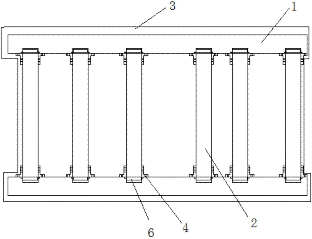
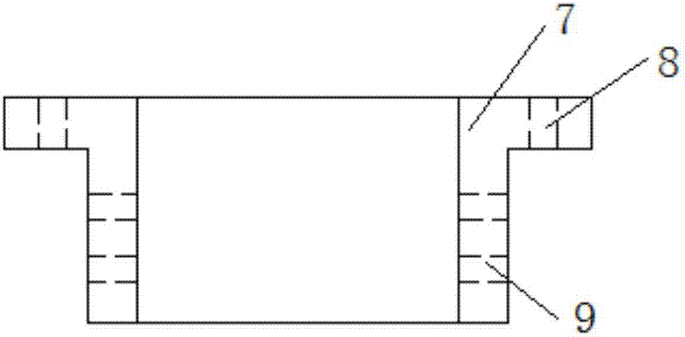
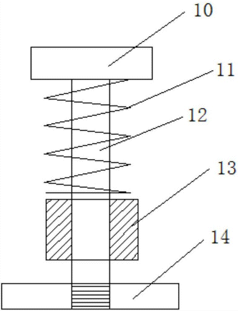
[0023] An automobile frame and its protective device, comprising a frame body composed of a longitudinal beam assembly 1 and a cross beam assembly 2, a protective plate assembly 3 is arranged below the frame body; the longitudinal beam assembly includes a longitudinal beam body And the connecting assembly 4 for connecting and fixing the crossbeam and the suspension mechanism 5 for installing the protective plate, the crossbeam assembly 2 includes the main crossbeam at both ends, the transmission crossbeam, the drive shaft crossbeam, the front side fuel tank crossbeam, and the rear side fuel tank crossbeam As well as the elastic limiter 6 arranged in the inner holes at both ends of each crossbeam, the protective plate assembly 3 includes a grooved protective plate matched with the vehicle frame itself, the two sides of the grooved protective plate are inclined outwards, and the protective plate The two ends and the middle part of the plate are equ...


PUM


Abstract

The invention discloses an automobile frame and a protection device thereof. The automobile frame comprises a frame body composed of a longitudinal beam assembly and a cross beam assembly, wherein a protection plate assembly is arranged below the frame body; the longitudinal beam assembly comprises longitudinal beam bodies, connection assemblies connected and fixed with cross beams, and a suspension mechanism for mounting protection plates; the cross beam assembly comprises main cross beams at two ends, a speed changer cross beam, a transmission shaft cross beam, a front fuel tank cross beam, a rear fuel tank cross beam as well as elastic limiting devices arranged in inner holes in two ends of each cross beam; and the protection plate assembly comprises a groove-shaped protection plate matched with the frame body, the two sides of the groove-shaped protection plate are obliquely arranged outwards, and connection rib plates connected with the suspension mechanism are mounted at the two ends and middle part of the protection plate. The automobile frame disclosed by the invention is simple in structure, convenient to weld and light in weight, and the stability of the frame is ensured; and the protection plate assembly has a buffer effect, thereby avoiding the breakage condition caused by direct impact and ensuring the service life of the frame and the protection plate.

Description

[0001] Technical field: [0002] The invention relates to the field of automobile components, and mainly relates to an automobile frame and a protective device thereof. [0003] Background technique: [0004] The car frame structure is an important component of the car. It mainly bears the supporting role and is used to install the main components of the car body. Therefore, the connection structure of the car frame itself needs to have good stability. We know that the existing beams are all If it is directly welded to the longitudinal beam, the force of the solder joint is too large, and it often breaks, which affects normal use and requires repair welding. Moreover, the bearing capacity of re-welding is not as good as before, and it is more likely to be damaged. Moreover, most of the existing cars do not have a protective plate structure. During their long-term use, a large amount of dust, rain, dirt, etc. will stick to the frame. If they are cleaned in time, the practical li...

Claims


Application Information

Patent Timeline
Patent Type & Authority Applications(China)
IPC IPC(8): B62D21/02B62D21/15
CPCB62D21/02B62D21/152
Inventor 周大浩宣洪祥
Owner 安徽宏祥工业循环经济开发有限公司
Learn More