Supercharge Your Innovation With Domain-Expert AI Agents!

Dobby cam drive

A technology of cam transmission and dobby machine, which is applied in the cam opening mechanism, textile, textile and paper making, etc., can solve the problems of not giving the specific structure of the cam transmission device, prolonging the service life of gears, complex structure, etc., to ensure stable transmission. performance, saving power consumption, and simplifying the structure

Active Publication Date: 2018-03-27
西安滨田特型机械有限公司
View PDF10 Cites 0 Cited by
  • Summary
  • Abstract
  • Description
  • Claims
  • Application Information

AI Technical Summary

Problems solved by technology

But this patent does not provide the specific structure of the cam drive
[0005] Although the "crank rocker type electronic jacquard machine" provided by the publication number CN106400249A discloses the specific structure of the cam drive to a certain extent, because the patent application scheme is proposed for the transformation of the crank rocker type electronic jacquard machine (see Paragraphs 0002 to 0004 of the description), so the structure of the power input mechanism that drives the front and rear support discs of the cam swing arm of the structural system of the cam transmission device is relatively complicated (for details, please refer to paragraphs 0039 to 0040 of the description of the patent application), If the aforementioned power input mechanism disclosed by this patent application is transferred to the dobby cam drive, the disadvantages in the following two aspects will be produced at least: one, due to the impossibility of driving the front support plate of the aforementioned cam swing arm (along with the direction The change can be called "cam swing arm left support plate", the same below) and the cam swing arm rear support plate (with the change of direction can be called "cam swing arm rear support plate", the same below) synchronous motion power input The shaft gear (also called "driving gear") and the supporting plate drive gear (also called "driven gear") driven by the power input shaft gear are housed in the casing and are protected by the casing at the same time. Lubricating oil keeps it in a good lubricating state all the time, because the non-limited number of tests done by the applicant shows that only by changing the aforementioned power input shaft gear and support disc drive gear from the external type in the prior art to the built-in type That is to say, it is transferred to the casing to ensure the stability of the transmission, reduce noise and vibration, significantly prolong the service life of the gears, and meet the requirements of high-speed motion; Drive the lower gear box, the power output shaft of the lower gear box of the lower gear box drives the cardan shaft through the lower coupling of the cardan shaft, and the cardan shaft drives the upper gear box through the upper coupling of the cardan shaft, and the upper gear box drives the The power output shaft of the upper gearbox drives the transition shaft through the power output shaft coupling of the upper gearbox, the transition shaft fixed with the front support plate of the cam swing arm drives the front support plate of the cam swing arm, and the front support plate of the cam swing arm drives a pair of At the same time, it forms a rolling pair with the rim (curved surface of the conjugate cam) of the conjugate cam (also called "heald lifting cam", the same below) and a swing arm movement that forms a sliding pair with the swing arm one-way seat fixed on the main shaft, and finally Make the main shaft move according to the requirements of the weaving process, so not only the structure is complicated, but also it is not conducive to saving energy consumption

Method used


Image

  • Dobby cam drive
  • Dobby cam drive

Examples


Embodiment Construction

[0020] In order to understand the technical essence and beneficial effects of the present invention more clearly, the applicant will describe in detail the following examples, but the descriptions of the examples are not intended to limit the solutions of the present invention. Equivalent transformations that are only formal but not substantive should be regarded as the scope of the technical solution of the present invention.

[0021] In the following descriptions, all concepts related to directionality or orientation of up, down, left, right, front and back are based on figure 1 The shown position status is a reference, so it cannot be understood as a special limitation on the technical solution provided by the present invention.

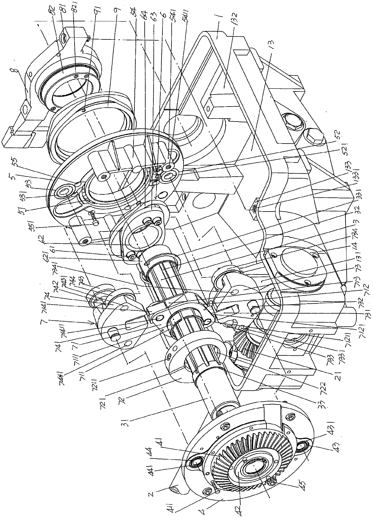
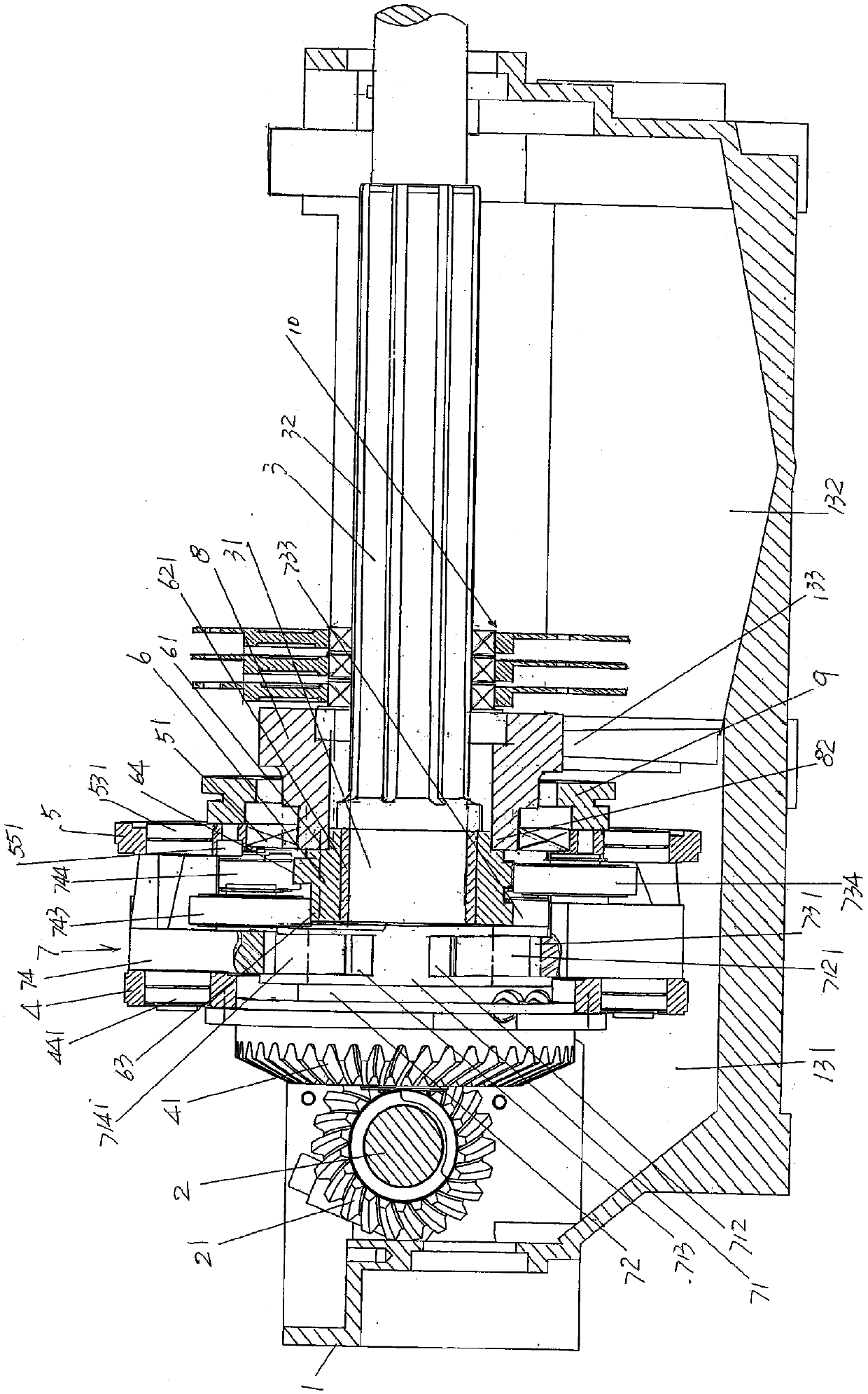
[0022] please see figure 1 , shows a casing 1 (also called "chassis", the same below) equipped with a casing cover (not shown in the figure), and a power input shaft cavity 131 is separated from the left end of the casing cavity 13 of the casing ...


PUM


Abstract

A dobby cam driving device comprises a housing provided with a cover, a power input shaft, a spindle, a cam swing arm left supporting disk and a cam swing arm right supporting disk, wherein a power input shaft cavity is formed in the left end of a housing cavity, a shedding arm cavity is formed in the right end of the housing cavity, the power input shaft is supported on the front-back housing wall of the housing at the left end, a power input shaft gear is arranged at the front end of the power input shaft, and the rear end of the power input shaft is connected with a power input shaft driving device, the spindle is located in the housing cavity, the cam swing arm left supporting disk and the cam swing arm right supporting disk correspond to each other and are fixedly connected, a supporting disk driving gear is arranged on the side, deviating from the cam swing arm right supporting disk, of the cam swing arm left supporting disk and is meshed with the power input shaft gear, the left end of the spindle is supported on the supporting disk driving gear, the right end of the spindle extends out of the housing, the cam swing arm right supporting disk is supported on a shedding cam fixing base, and a shedding cam and a cam swing arm mechanism are located between the cam swing arm left supporting disk and the cam swing arm right supporting disk. The dobby cam driving device ensures driving stability, reduces noise, is good in lubrication and long in service life, the structure is simplified, a power transfer link is omitted, and electricity consumption is reduced.

Description

technical field [0001] The invention belongs to the technical field of textile machinery, and in particular relates to a cam transmission device of a dobby machine. Background technique [0002] The dobby is one of the opening parts of the loom that converts the signal of the fabric pattern into the opening action and drives the heald frame of the loom to lift the heald up and down. The dobby is divided into negative type and active type according to the different opening forms. There are two types. [0003] In the aforementioned passive dobby, its main components such as the broach, push knife and draw hook move in a reciprocating motion, and return to heald in the form of a spring. However, with the wide application of shuttleless looms, especially the continuous increase in the speed of looms, the negative dobby machine not only consumes a lot of kinetic energy due to the impact of motion inertia, but also is difficult to ensure the high-speed and stable movement of the ...

Claims


Application Information

Patent Timeline
Patent Type & Authority Patents(China)
IPC IPC(8): D03C5/00
CPCD03C5/00
Inventor 金永良金良根吕雪奎徐振宇杨佳敏
Owner 西安滨田特型机械有限公司
Features
  • R&D
  • Intellectual Property
  • Life Sciences
  • Materials
  • Tech Scout
  • Unparalleled Data Quality
  • Higher Quality Content
  • 60% Fewer Hallucinations
Learn More