Rotary magnetorheological damper

A magneto-rheological damper, rotary type technology, applied in the direction of shock absorber, shock absorber, liquid shock absorber, etc., can solve the problem that the deployment part cannot meet the design requirements of vibration reduction, and is not suitable for rotary deployment mechanism, damping In order to achieve the effect of compact structure, large damping torque, easy processing and assembly

Inactive Publication Date: 2017-08-11
SHENYANG INST OF AUTOMATION - CHINESE ACAD OF SCI
View PDF4 Cites 6 Cited by
  • Summary
  • Abstract
  • Description
  • Claims
  • Application Information

AI Technical Summary

Problems solved by technology

[0003] Most of the current magneto-rheological dampers are still mainly piston rod-type in structure, and their length and size are relatively large. Installation in places with limited space is limited by volume.
The use of a small damper with poor damping effect will easily lead to the failure of the deployment part to meet the design requirements for vibration reduction; the characteristics of the linear reciprocating motion of the piston rod are not suitable for the vibration reduction of the rotary deployment mechanism.

Method used


Image

  • Rotary magnetorheological damper
  • Rotary magnetorheological damper
  • Rotary magnetorheological damper

Examples


Embodiment Construction

[0018] The present invention will be described in further detail below in conjunction with the accompanying drawings.

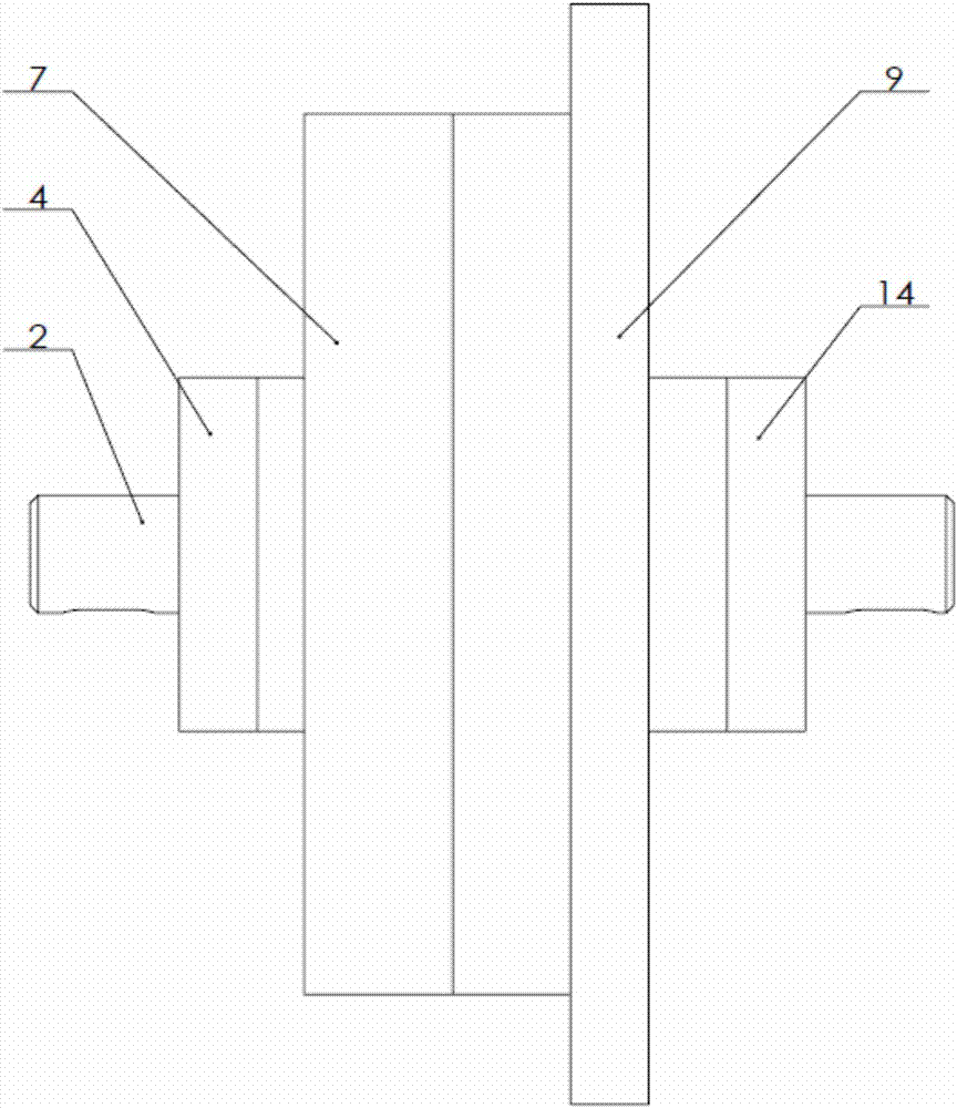
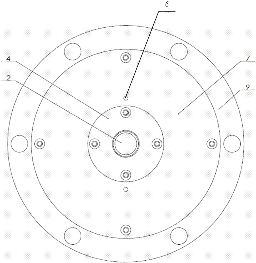
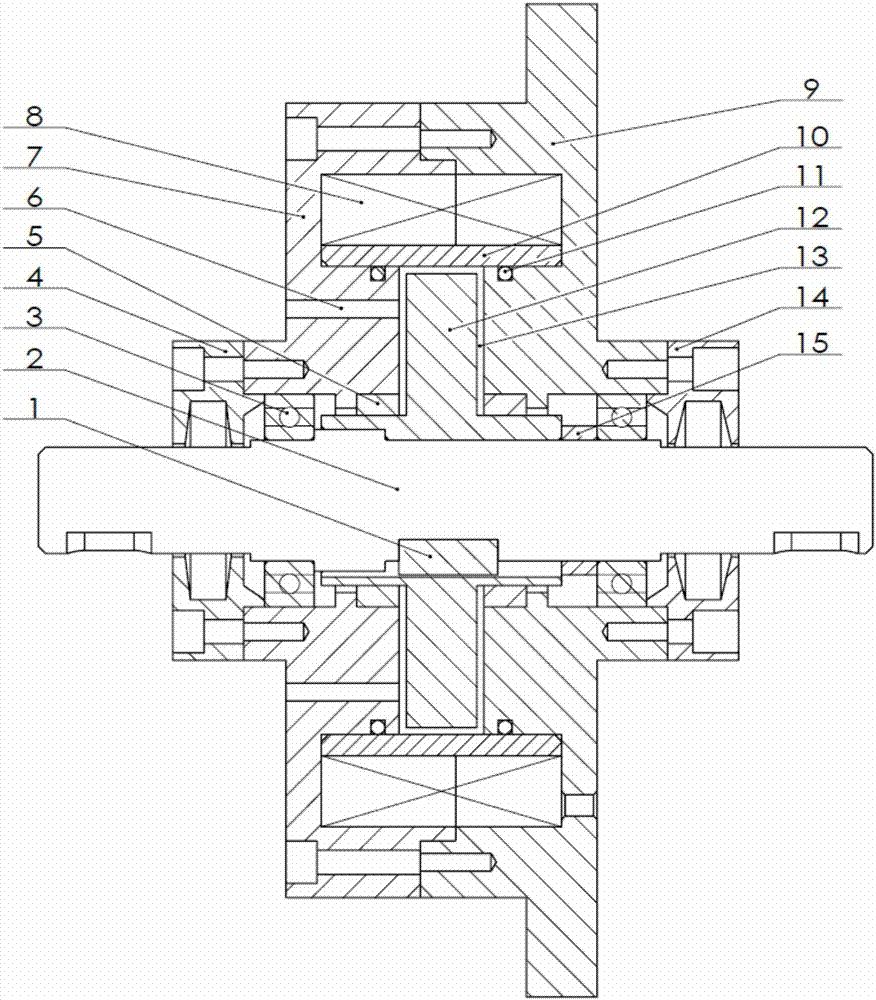
[0019] Such as Figure 1~3 As shown, the present invention includes rotating shaft 2, left end cover 4, oil seal 5, housing, excitation coil 8, copper ring 10, damping disc 12, right end cover 14 and magnetic isolation ring, wherein the housing is divided into left housing 7 And the right housing 9 is fixedly connected by bolts. The outer diameter of the right housing 9 is larger than the diameter of other parts to form a flange for connection. There are a plurality of bolt holes uniformly distributed along the circumference of the flange for damping The overall installation of the device.

[0020] The left end cover 4 is sealed and connected with the left housing 7, the right end cover 14 is sealed and connected with the right housing 9, and the rotating shaft 2 passes through the left end cover 4, the left housing 7, the right housing 9 and the right end c...


PUM


Abstract

The invention relates to a damper, in particular to a rotary magnetorheological damper. The left and right sides of a shell are tightly connected with left and right end covers; a rotating shaft penetrates through the left and right end covers and the shell in sequence, and is rotationally connected with the shell; a damping disc piece is accommodated in the shell, and rotates along with the rotating shaft; a damping gap is formed between the damping disc piece and the inner surface of the shell; the shell is provided with an injection hole for communicating with the damping gap and injecting magnetorheological fluid in the damping gap; the magnetorheological fluid in the damping gap is sealed through an oil seal arranged between the rotating shaft and the shell; a copper ring positioned at the outer periphery of the damping disc piece is arranged in the shell, and is tightly contacted with the shell; a magnet exciting coil is wound on the outer surface of the copper ring; and the control of a damping torque generated to the damper can be realized through the magnet exciting coil. The rotary magnetorheological damper can realize semi-active control of the damping torque, is wide in torque control range, is low in electric energy consumption, and is high in reliability and stability in long-time system working.

Description

technical field [0001] The invention relates to a damper, in particular to a rotary magnetorheological damper. Background technique [0002] Existing dampers are generally composed of cylinders, pistons, piston rods, magneto-rheological fluids and guide rods. The pistons can perform reciprocating linear motions in the cylinders. There are small holes on the pistons or gaps are left between the pistons and the cylinders to act as dampers. The damping hole is filled with magnetorheological fluid in the oil cylinder. When the load changes to produce an impact, the driving piston reciprocates in a straight line in the cylinder, so that the magnetorheological fluid passes through the small hole on the piston or the gap between the piston and the cylinder; in addition, the intensity of the magnetic field can also be changed by changing the intensity of the input current , and then change the shear yield strength of the magnetorheological fluid to realize the control of the dampin...

Claims


Application Information

Patent Timeline
Patent Type & Authority Applications(China)
IPC IPC(8): F16F9/12F16F9/53
CPCF16F9/12F16F9/535
Inventor 刘金国刘志波倪智宇谢华龙冯靖凯
Owner SHENYANG INST OF AUTOMATION - CHINESE ACAD OF SCI
Why Eureka
Try Eureka