Suspension type drying room structure

A hanging type and drying room technology, applied in the direction of drying, drying machine, progressive drying machine, etc., can solve the problems of reducing the comfort of the operator's working environment, unable to dry the product, and poor sealing of the drying room , to achieve the effect of reducing human workload, improving drying processing efficiency and reducing energy consumption

Inactive Publication Date: 2017-08-11
JIANGSU YONGYI ENVIRONMENTAL PROTECTION TECH CO LTD
View PDF12 Cites 7 Cited by
  • Summary
  • Abstract
  • Description
  • Claims
  • Application Information

AI Technical Summary

Problems solved by technology

[0003] When the material is drying, the insulation effect in the drying room must be good, so that the material can be continuous and complete during the drying operation. However, the sealing of the existing drying room is not good, and heat transfer phenomenon is easy to occur inside and outside the drying room, resulting in the overall failure of the drying room. The insulation effect is poor, so that the product cannot be dried in an ideal constant temperature environment, and in severe cases, the material will be scrapped;
[0004] In addition, the composition panels of the drying room are easily deformed under high temperature for a long time, and the heat insulation effect is poor, which will easily lead to an increase in the ambient temperature around the drying room and reduce the comfort of the operator's working environment

Method used


Image

  • Suspension type drying room structure
  • Suspension type drying room structure
  • Suspension type drying room structure

Examples


Embodiment

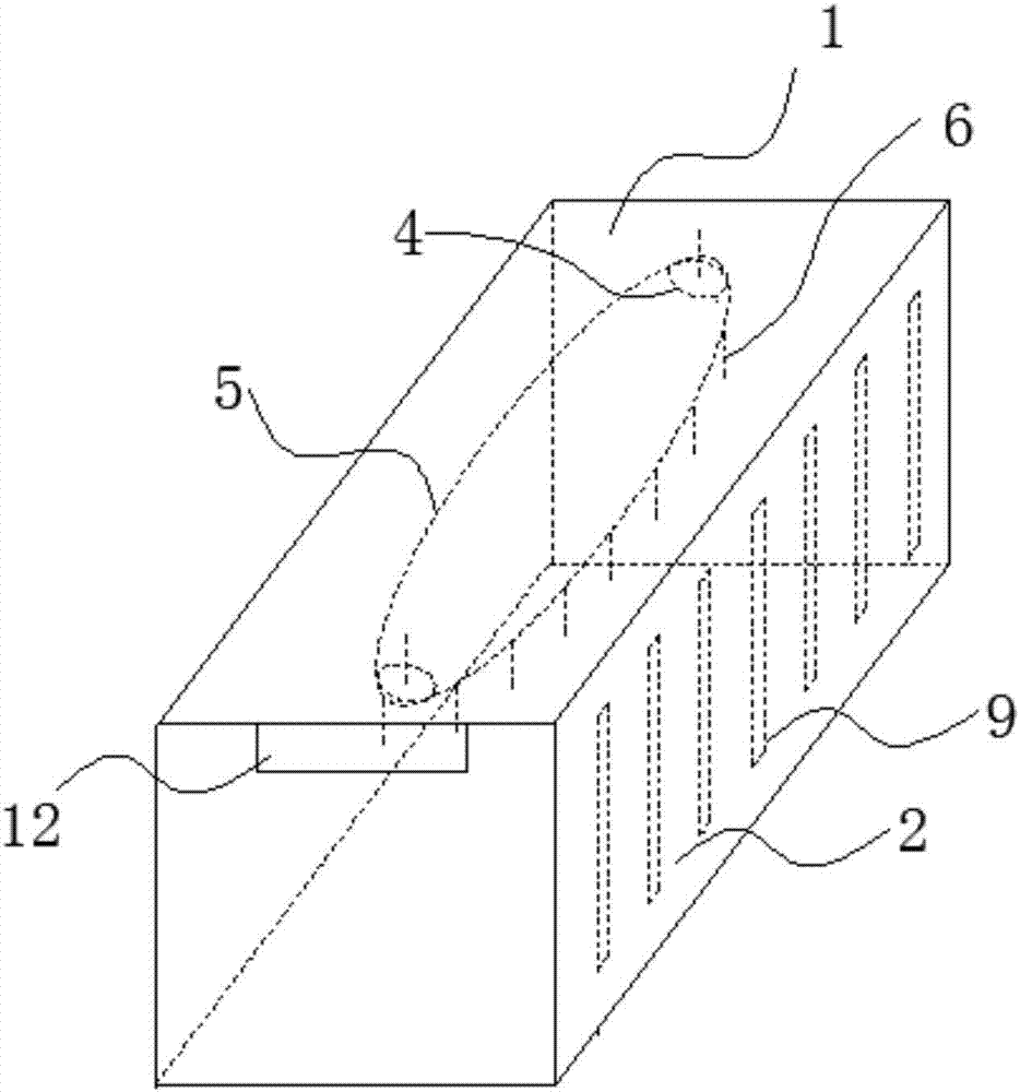
[0037] Embodiment: a kind of suspended drying room structure, as Figure 1-6 As shown, it includes a three-dimensional frame with openings at the front and rear ends consisting of top plate 1, side plates 2 on left and right sides, and bottom plate 3. The inner surface of the top plate 1 is provided with a conveying structure, and the conveying structure includes a drive motor 4, Horizontal circulating conveyor chain 5 and several suspension rods 6, the drive motor 4 is located at both ends of the circular conveyor chain 5 and is fixedly connected with the top plate 1, and the upper ends of all the suspension rods 6 are equidistantly fixed on Move on the circulating conveyor chain 5 and driven by the circulating conveyor chain 5;

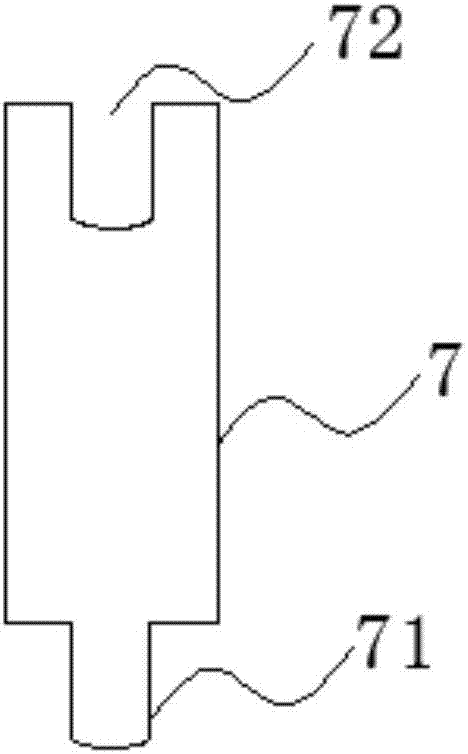
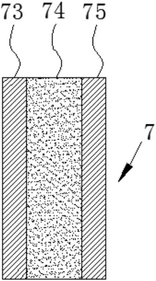
[0038] The top plate 1, the two side plates 2 and the bottom plate 3 are all spliced ​​by several heat insulating plates 7, one end of the heat insulating plate 7 is a male end 71 and the opposite end is a female end 72 , the male end 71 and the ad...


PUM


Abstract

The invention discloses a suspension type drying room structure. The suspension type drying room structure comprises a three-dimensional frame, wherein the three-dimensional frame is composed of a top plate, a left side plate, a right side plate and a bottom plate, and openings are formed in the front end and the rear end of the three-dimensional frame correspondingly. A conveying structure is arranged on the inner surface of the top plate and comprises driving motors, a circulating conveying chain in the horizontal direction and a plurality of suspension rods, wherein the driving motors are located at the two ends of the circulating conveying chain and fixedly connected with the top plate; and the upper ends of the suspension rods are fixed to the circulating conveying chain at equal intervals, and the suspension rods are driven by the circulating conveying chain to move. A plurality of heating pipes are distributed on the side plates at interval intervals. A plurality of temperature sensors are distributed on the top plate, the side plates and the bottom plate correspondingly. The suspension type drying room structure further comprises a PLC, and the driving motors, the heating pipes and the temperature sensors are all electrically connected with the PLC. The suspension type drying room structure is suitable for suspension drying of big articles or heavyweight products, heat-preservation and heat-insulation effects are good, the constant-temperature state at the temperature of 160-170 DEG C is maintained, and the product drying effect is guaranteed.

Description

technical field [0001] The invention belongs to the technical field of drying equipment, in particular to a drying room. Background technique [0002] The drying room, also known as the drying and curing room, is a hot air circulation system for curing the surfaces of large electrical appliances, motors, paints, chemicals, etc., or for moisture drying of food and various products. [0003] When the material is drying, the insulation effect in the drying room must be good, so that the material can be continuous and complete during the drying operation. However, the sealing of the existing drying room is not good, and heat transfer phenomenon is easy to occur inside and outside the drying room, resulting in the overall failure of the drying room. The insulation effect is poor, so that the product cannot be dried in an ideal constant temperature environment, and in severe cases, the material will be scrapped; [0004] In addition, the composition panels of the drying room are ...

Claims


Application Information

Patent Timeline
Patent Type & Authority Applications(China)
IPC IPC(8): F26B15/04F26B25/06F26B25/00F26B25/10F26B25/12F26B23/06
CPCF26B15/04F26B23/06F26B25/003F26B25/06F26B25/10F26B25/12
Inventor 蒋伟
Owner JIANGSU YONGYI ENVIRONMENTAL PROTECTION TECH CO LTD
Why Eureka
Try Eureka