
An off-axis reflective optical antenna and system

An optical antenna and off-axis reflection technology, applied in the direction of optics, optical components, instruments, etc., can solve the problems of reduced fiber coupling efficiency at the receiving end, failure to meet system requirements, and weak optical signals, so as to avoid adverse effects, install and debug Simple and convenient, high coupling efficiency effect

Active Publication Date: 2020-04-07
北京北方群星科技发展有限公司
View PDF6 Cites 0 Cited by
  • Summary
  • Abstract
  • Description
  • Claims
  • Application Information

AI Technical Summary

Problems solved by technology

Traditional lens-type optical antennas, due to the chromatic aberration between the communication laser and the alignment laser, even if the alignment is achieved using the alignment laser, the coupling efficiency of the optical fiber at the receiving end will still be reduced, and the extracted optical signal will be weak, which cannot meet the requirements of the system. Requirements

Method used


Image

  • An off-axis reflective optical antenna and system
  • An off-axis reflective optical antenna and system

Examples


Embodiment Construction

[0025] In order to make the objectives, technical solutions and advantages of the present invention clearer, the technical solutions of the present invention will be described in detail below. Obviously, the described embodiments are only a part of the embodiments of the present invention, rather than all the embodiments. Based on the embodiments of the present invention, all other implementations obtained by a person of ordinary skill in the art without creative work shall fall within the protection scope of the present invention.

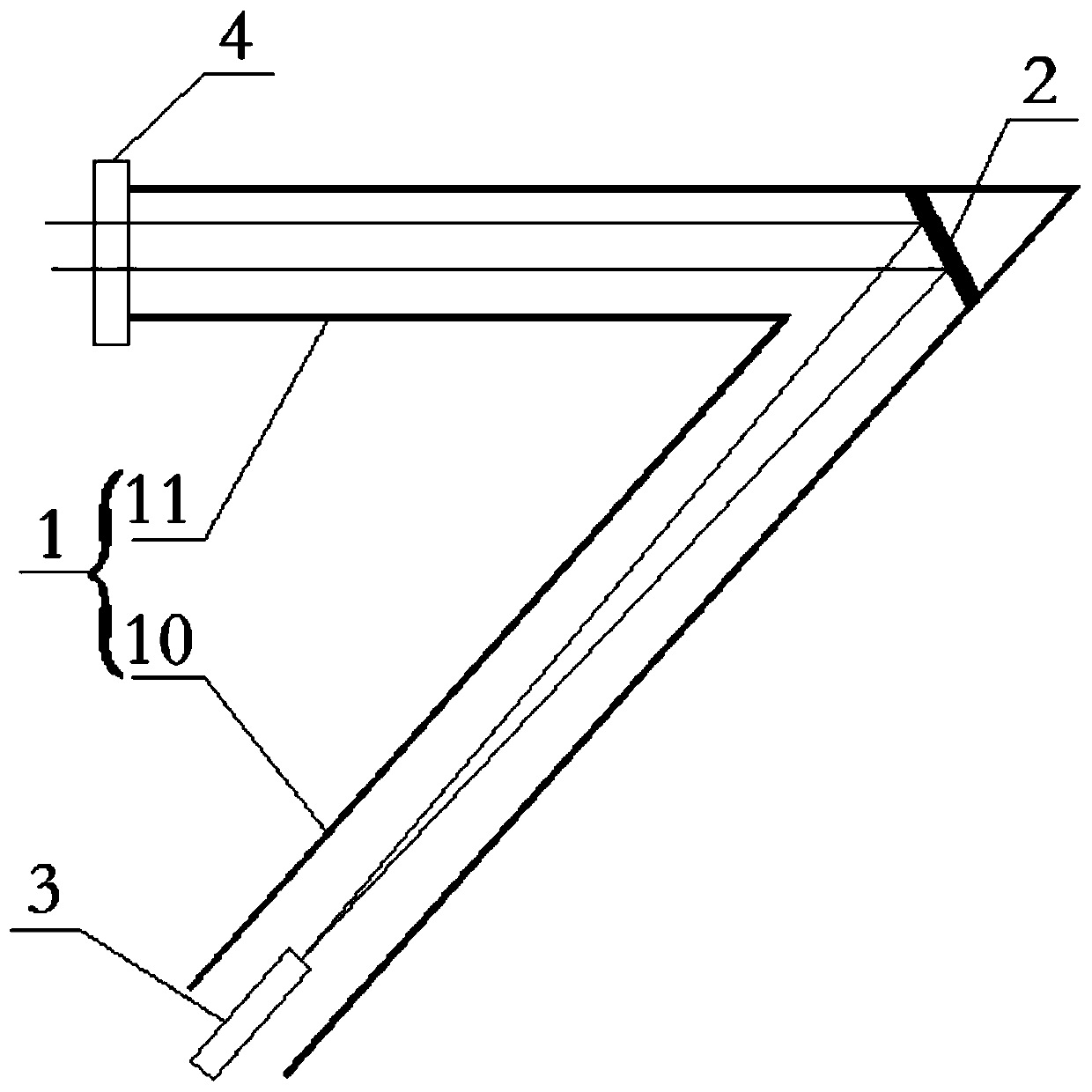
[0026] Such as figure 1 As shown, the present invention provides an off-axis reflective optical antenna, comprising: a housing 1 and an off-axis parabolic mirror 2 arranged in the housing 1, and an optical fiber interface arranged at one end of the housing 1. 3; The optical fiber interface 3 is set at the focal point of the off-axis parabolic mirror 2, and the optical fiber interface 3 is used to transmit or receive signal light for transmission.

[0...


PUM


Abstract

The invention relates to an off-axis reflective optical antenna comprising a housing, an off-axis parabolic mirror arranged inside the housing, and a fiber interface arranged at one end of the housing. The fiber interface is arranged at a focal point of the off-axis parabolic mirror; and the fiber interface is used for transmitting or receiving signal light and then carrying out transmission. Compared with the prior art, the off-axis reflective optical antenna has the following advantages: a few of devices are used by the antenna; the fiber interface is arranged at the focal point of the off-axis parabolic mirror directly, so that installation and debugging becomes simple and convenient; with the off-axis parabolic mirror and the off-axis collimating and coupling way, the coupling efficiency is high; and the antenna has the same optical path for light of different wave bands, so that the adverse effect on the alignment debugging by the chromatic aberration of different wavelengths can be avoided.

Description

Technical field [0001] The invention belongs to the technical field of space laser communication, and particularly relates to an off-axis reflective optical antenna and system. Background technique [0002] In the laser communication system, the transceiver terminal used for space optical communication must be aligned before the laser communication starts, and this alignment requires high accuracy. The existing spatial optical communication optical antenna is generally a transmissive optical lens system. This optical antenna adopts the principle of converging parallel light through a lens. However, the laser wavelength generally used for communication is 1550nm or 1310nm invisible light. The alignment adjustment work at both ends of the communication system brings great difficulties. Therefore, the best solution at present is to first use the laser in the visible light band for system alignment, and then use invisible light to achieve laser communication. [0003] However, this me...

Claims


Application Information

Patent Timeline
Patent Type & Authority Patents(China)
IPC IPC(8): G02B17/06
CPCG02B17/0668
Inventor 刘博
Owner 北京北方群星科技发展有限公司
Learn More