State latch circuit and high voltage monitoring and protection device using the circuit

A state lock and circuit technology, applied to overload protection devices, measuring devices, components of electrical measuring instruments, etc., can solve problems such as false protection, misjudgment, and impact on reliability

Active Publication Date: 2021-07-06
SHENZHEN STS MICROELECTRONICS CO LTD
View PDF7 Cites 0 Cited by
  • Summary
  • Abstract
  • Description
  • Claims
  • Application Information

AI Technical Summary

Problems solved by technology

However, it is easy to misjudge the normal overvoltage phenomenon, cause false protection, and affect the reliability of protection.
And it takes a certain amount of time to start and stop the high-voltage and high-current power supplies
Frequent start and stop has a great negative impact on the life of the equipment

Method used


Image

  • State latch circuit and high voltage monitoring and protection device using the circuit
  • State latch circuit and high voltage monitoring and protection device using the circuit
  • State latch circuit and high voltage monitoring and protection device using the circuit

Examples


no. 1 example

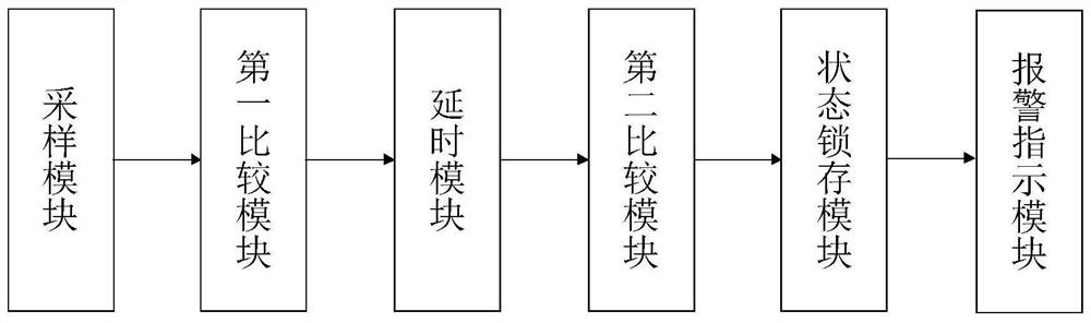
[0035] Such as figure 2 As shown, the present invention provides a state latch circuit, including a sampling module, a state latch module, and a control module. The sampling module includes a first sampling input terminal and a second sampling input terminal, and the first sampling input terminal is used for Connect the first sampling point of the test circuit, the second sampling input end is used to connect the second sampling point of the test circuit, the output end of the sampling module is connected to the input end of the state latch module, the state latch module The output end is connected to the input end of the control module, and the output of the control module controls the test circuit. Specific sampling points such as Figure 5 As shown, A is the first sampling point, and B is the second sampling point. The voltage sampling signal of point B is synchronized with the trigger control of point A, so the sampling signal of the sampling module can basically keep s...

no. 2 example

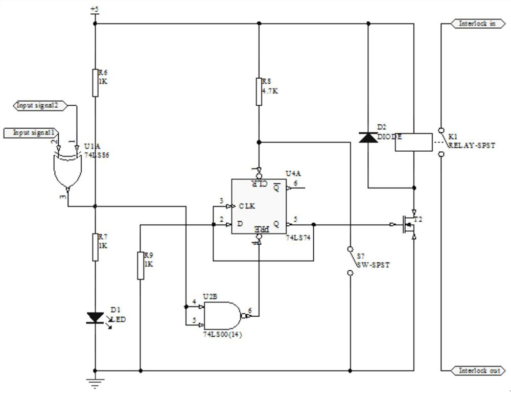
[0047] Such as image 3 Shown is the schematic circuit diagram of the second embodiment provided by the present invention. This embodiment is based on the first embodiment, and further includes:

[0048] The delay module is set between the first comparison module and the state latch module, to quickly and accurately detect voltage and current, and distinguish true and false overcurrent. The input signal of the test circuit collected by the sampling module will output a short abnormal signal due to incomplete synchronization, while the state latch module cannot judge whether it is true or false overcurrent, and the delay module is used to delay the abnormal signal , the delay time is set to t1. The delay time can be adjusted according to the actual situation of the product under test through the capacity of the capacitor C2 and the resistance value of the adjustable resistor to realize adjustable detection time, high accuracy of overvoltage and overcurrent detection, and avoi...

no. 3 example

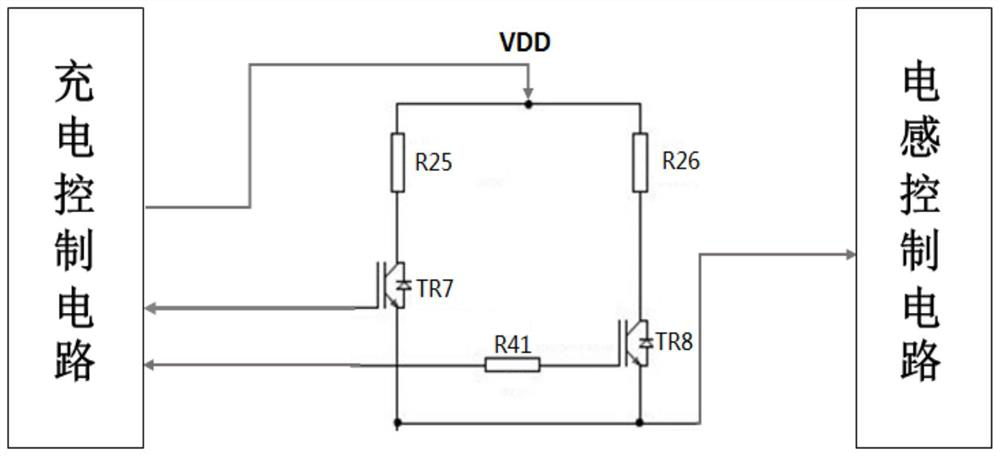
[0051] Such as Figure 4 , 5 As shown, the present invention also provides a high-voltage monitoring and protection device, including the above-mentioned state latch circuit. The first sampling input terminal of the sampling module is used to detect the control signal of the test circuit, and the second sampling input terminal is used to detect the high voltage power supply state of the test circuit in real time. Specific sampling points such as Figure 5 As shown, A is the first sampling point, and B is the second sampling point. The voltage sampling signal of point B is synchronized with the trigger control of point A, so the sampling signal of the sampling module can basically keep synchronous.

[0052] This high-voltage monitoring and protection device is connected to the detection circuit, and compares the first sampling signal with the second sampling signal. If an abnormal signal is detected and the time exceeds the set delay time T1, the abnormal signal will be sen...


PUM


Abstract

The invention discloses a state latch circuit, which includes a sampling module, a state latch module, and a control module; the sampling module includes a first sampling input terminal and a second sampling input terminal, and the first sampling input terminal is used for connecting a test circuit The first sampling point, the second sampling input is used to connect the second sampling point of the test circuit, the output of the sampling module is connected to the input of the state latch module, the output of the state latch module The terminal is connected to the input terminal of the control module, and the output of the control module controls the test circuit. The invention can monitor the change of the voltage signal in real time, and control and protect the test equipment.

Description

technical field [0001] The invention relates to the application field of electronic technology, in particular to a state latch circuit and a high-voltage monitoring and protection device using the circuit. Background technique [0002] With the development of power electronics technology, power devices are widely used in uninterruptible power supplies, frequency conversion speed control devices and other related products due to their performance advantages and convenient control. When an overcurrent or short circuit occurs, the current flowing through the power device is much greater than the rated value, causing the temperature of the die of the power device to rise rapidly, eventually leading to burnout. Therefore, it is necessary to test the performance of power devices before they can be put into application. [0003] In the tested circuit, as figure 1 As shown, it is an equivalent circuit for testing a power device by DS4 equipment in the prior art. The test circuit s...

Claims


Application Information

Patent Timeline
Patent Type & Authority Patents(China)
IPC IPC(8): G01R1/36G01R1/30
Inventor 李伟志米鹏李伟周杰
Owner SHENZHEN STS MICROELECTRONICS CO LTD
Why Eureka
Try Eureka