
Binocular near-infrared imaging system and blood vessel recognition method

A technology of near-infrared imaging and binocular photography, which is applied in the field of medical devices and can solve the problems of insufficient precision of blood vessels

Inactive Publication Date: 2017-08-15
中科微光医疗研究中心(西安)有限公司
View PDF9 Cites 19 Cited by
  • Summary
  • Abstract
  • Description
  • Claims
  • Application Information

AI Technical Summary

Problems solved by technology

[0004] Although the above-mentioned patent documents disclose the use of near-infrared light to assist in judging the position of blood vessels, the recognition accuracy of blood vessels is not enough, because in practical applications, the recognition of blood vessels not only needs to identify its two-dimensional coordinates in skin tissue, but also It is necessary to identify its three-dimensional coordinates in space, so that it can truly assist medical staff to complete manual puncture, and it is more conducive to the machine to complete automatic puncture

Method used


Image

  • Binocular near-infrared imaging system and blood vessel recognition method
  • Binocular near-infrared imaging system and blood vessel recognition method
  • Binocular near-infrared imaging system and blood vessel recognition method

Examples


Embodiment 1

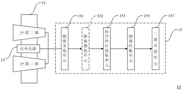
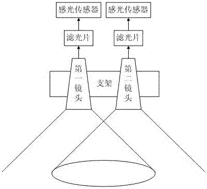
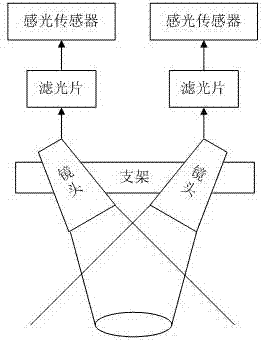
[0059] See figure 1 , figure 1 It is a schematic structural diagram of a binocular near-infrared imaging system provided by an embodiment of the present invention. This system 10 comprises binocular camera mechanism 11, infrared light source 13 and processor 15, and this processor 15 is electrically connected with described binocular camera mechanism 11 and described infrared light source 13 respectively to collect by described binocular camera mechanism 11. The obtained infrared images are processed for three-dimensional blood vessel image recognition.

[0060] Wherein, the processor 15 includes an image acquisition unit 151 , a blood vessel feature extraction unit 153 , an image matching unit 155 and a three-dimensional reconstruction unit 157 . The image collection unit 151 is used to control the binocular camera mechanism 11 to collect infrared images of the skin tissue to form a first image and a second image; the blood vessel feature extraction unit 153 is used to anal...

Embodiment 2

[0071] See Figure 10 , Figure 10 It is a schematic flowchart of a blood vessel identification method provided by an embodiment of the present invention. This embodiment describes in detail the blood vessel identification method of the present invention on the basis of the foregoing embodiments. Specifically, the method may include the following steps:

[0072] Step a, collecting the first image and the second image of the same part of the skin tissue under the irradiation of an infrared light source;

[0073] Step b, performing blood vessel feature extraction on the first image and the second image to form a first blood vessel image and a second blood vessel image;

[0074] Step c, performing stereo matching on the first blood vessel image and the second blood vessel image to form a three-dimensional blood vessel image to complete blood vessel identification.

[0075] For step a, the image acquisition unit sends an instruction to control the infrared light source to irra...


PUM


Abstract

The invention relates to a binocular near-infrared imaging system and a blood vessel recognition method. The binocular near-infrared imaging system includes: a binocular camera shooting mechanism (11), an infrared light source (13), and a processing unit (15); and the processing unit (15) is electrically connected to the binocular camera shooting mechanism (11) and the infrared light source (13) so as to use infrared images acquired by the binocular camera shooting mechanism (11) to perform three-dimensional image recognition processing on blood vessels. According to the mechanism that the near-infrared light of hemoglobin in the blood vessels is different from that of other tissues and the principle of parallax of binocular images of a binocular visual imaging mechanism, the binocular visual imaging mechanism and the infrared light source can perform image acquisition and processing on skin tissues so as to achieve spatial three-dimensional recognition of the blood vessels.

Description

technical field [0001] The invention relates to the technical field of medical devices, in particular to a binocular near-infrared imaging system and a blood vessel identification method. Background technique [0002] Vascular puncture failure is one of the fuses leading to medical disputes. During clinical vascular puncture, due to hypertrophy of the skin of some patients, small blood vessels are difficult to find, and some trauma patients are unconscious and unconscious due to excessive blood loss, and the blood vessels are not filled. , leading to the medical staff not being able to find blood vessels during intravenous injection, and infants and young children due to their physiological reasons and personality characteristics, it is difficult for medical staff to find blood vessels, which greatly increases the time of medical staff on a single patient, which not only It makes the patient suffer from physical pain and mental tension, and also makes the doctor-patient rela...

Claims


Application Information

Patent Timeline
Patent Type & Authority Applications(China)
IPC IPC(8): A61B5/00
CPCA61B5/0064A61B5/0077A61B5/489A61B5/7203
Inventor 常珂珂党磊李卓杨文波朱锐李嘉男
Owner 中科微光医疗研究中心(西安)有限公司
Learn More