A compressed air cycle power device

A technology of circulating power and compressed air, which is applied to components of pumping devices for elastic fluids, machines/engines, liquid fuel engines, etc., can solve the problems of reduced utilization of compressed air and waste of energy, and achieve reduction of emissions, The effect of avoiding waste

Inactive Publication Date: 2019-08-02
王旭明
View PDF6 Cites 0 Cited by
  • Summary
  • Abstract
  • Description
  • Claims
  • Application Information

AI Technical Summary

Problems solved by technology

[0003] As we all know, compressed air can be used to do work, but the compressed air in actual industrial production is directly discharged after doing work. However, the compressed air still has a certain pressure after doing work, so the utilization rate of compressed air is greatly reduced, that is, a considerable part is wasted energy, which contradicts the theory of improving current energy shortages

Method used


Image

  • A compressed air cycle power device
  • A compressed air cycle power device
  • A compressed air cycle power device

Examples


Embodiment 1

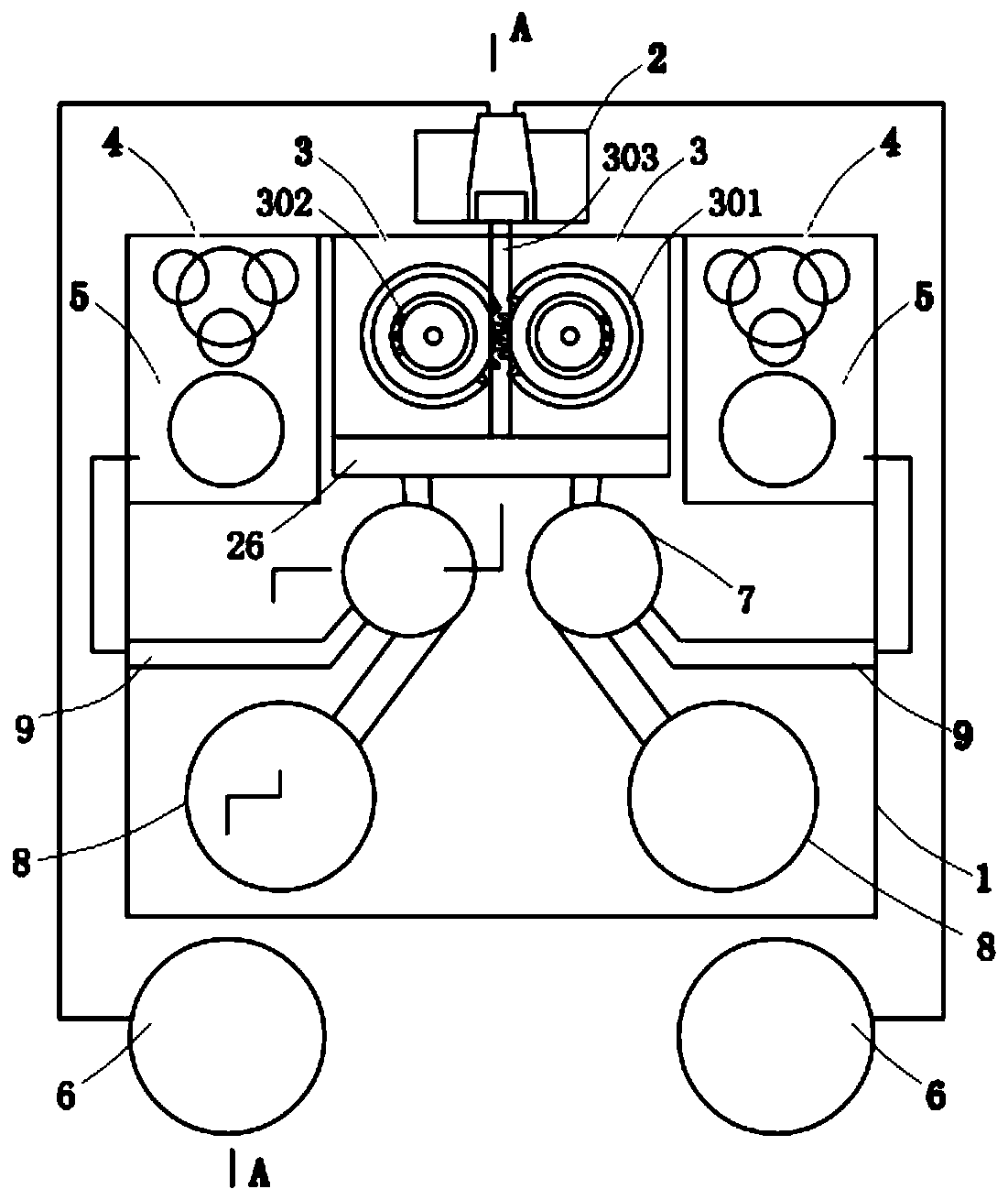
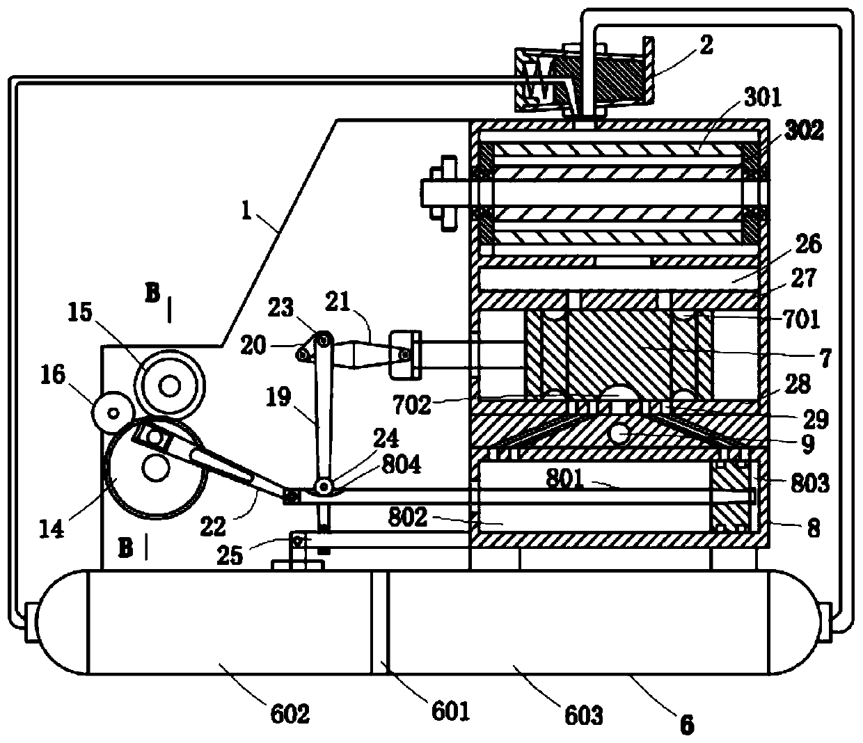
[0023] Such as Figure 1 to Figure 4As shown, the present invention provides a compressed air cycle power device, the cycle power device includes a frame 1, and an air storage tank 6 is fixedly installed on the frame 1, and a partition 601 is arranged in the gas storage tank 6, and the partition 601 will The internal space of the air storage tank 6 is divided into a high-pressure chamber 602 and a low-pressure chamber 603. The pressure of the compressed air in the high-pressure chamber 602 is higher than the pressure of the compressed air in the low-pressure chamber 603. The pressure difference needs to be set according to the needs. Here, usually The pressure in the high-pressure chamber 602 is 15 kilograms, and the pressure in the low-pressure chamber 603 is 10 kilograms. The air mixing valve 2 is arranged on the frame 1. One air inlet of the air mixing valve 2 is connected to the high-pressure chamber 602, and the other air inlet is connected to the air inlet. The low-press...

Embodiment 2

[0028] Such as Figure 1 to Figure 4 As shown, the present invention provides a compressed air cycle power plant, the structure of which is basically the same as that of Embodiment 1. The difference is that on the basis of Embodiment 1, the following features are added, and further improvements are made to improve performance of the present invention.

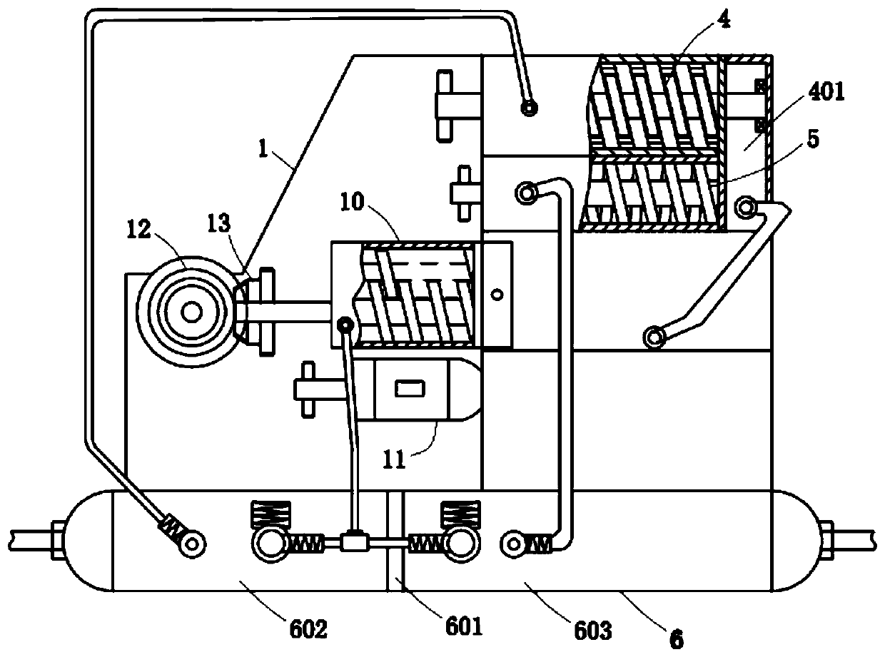
[0029] An external force motor 11 is installed on the frame 1, and the external force motor 11 is connected to the screw shaft of the screw air compressor 10 through a clutch. The function of the external force motor 11 is to start the external force motor 11 to drive the screw air compressor 10 to work before work , respectively inflate the high-pressure chamber 602 and the low-pressure chamber 603 of the air storage tank 6, so that the pressure difference between the high-pressure chamber 602 and the low-pressure chamber 603 is formed. After reaching the pressure difference, the external force motor 11 and the screw air compr...

Embodiment 3

[0031] Such as Figure 1 to Figure 4 As shown, the present invention provides a compressed air cycle power plant, the structure of which is basically the same as that of Embodiment 1. The difference is that on the basis of Embodiment 1, the following features are added, and further improvements are made to improve performance of the present invention.

[0032] There are two gas storage tanks 6, the high-pressure chambers 602 of the two gas storage tanks 6 are connected, and the low-pressure chambers 603 of the two gas storage tanks 6 are connected. On the one hand, the equipment is symmetrical, and on the other hand, the gas storage capacity can be relatively increased. Further improve the energy conversion rate of compressed air.

[0033] When in use, first artificially create a pressure difference, start the external force motor 11, respectively inflate the high-pressure chamber 602 and the low-pressure chamber 603 of the air storage tank 6, so that the pressure of the comp...


PUM


Abstract

The invention relates to a compressed air circulation power device, and belongs to the technical field of power equipment. The device comprises a frame; an air storage tank is fixedly mounted on the frame; a high-pressure cavity and a low-pressure cavity are formed in the air storage tank; the frame is provided with an air mixing valve for communicating the high-pressure cavity with the low-pressure cavity; two double-shaft gear motors are mounted on the frame; an outlet of each motor airflow channel is connected with an air distribution chamber; three-screw pumps and single-screw pumps are respectively mounted on the left and right sides of the frame; screw shafts of the single-screw pumps and screw shafts of the three-screw pumps on the same sides are respectively in transmission connection with two gear shafts; a main cylinder is respectively arranged below each air distribution chamber; a main piston rod is movably mounted in the main cylinder; the two main piston rods are respectively connected with one driving gear through rocking arms; the two rocking arms are synchronized, and have a phase difference; and power output gears engaged with the driving gears are rotationally mounted on the frame. The device can recycle compressed air, increases the energy conversion rate of the compressed air, and is widely applied to industrial production.

Description

technical field [0001] The invention relates to the technical field of power equipment, in particular to a compressed air cycle power device. Background technique [0002] With the development of the national economy, the ensuing energy shortage problem is becoming more and more serious. Therefore, people pay more and more attention to the full utilization of natural resources. At present, solar energy is widely used, but solar energy is mostly used in power generation, agriculture and heating. , it is difficult to use in industrial production. Air power is also an important natural resource, which is mainly expressed as compressed air, which is convenient for use in industrial production. [0003] As we all know, compressed air can be used to do work, but the compressed air in actual industrial production is directly discharged after doing work. However, the compressed air still has a certain pressure after doing work, so the utilization rate of compressed air is greatly r...

Claims


Application Information

Patent Timeline
Patent Type & Authority Patents(China)
IPC IPC(8): F04C23/00F04C23/02F04C29/12F03C2/08
CPCF03C2/08F04C23/001F04C23/02F04C29/12
Inventor 王旭明王帅杰
Owner 王旭明
Why Eureka
Try Eureka