
Power supply circuit, terminal and voltage output method

A power output and power circuit technology, applied in the electronic field, can solve the problem of high circuit cost

Pending Publication Date: 2017-08-15
NUBIA TECHNOLOGY CO LTD
View PDF10 Cites 0 Cited by
  • Summary
  • Abstract
  • Description
  • Claims
  • Application Information

AI Technical Summary

Problems solved by technology

[0005] The main technical problem to be solved by the present invention is to provide a power supply circuit, a terminal and a voltage output method to solve the problem in the prior art that the circuit that generates electricity can only obtain a specific voltage value or the circuit that produces two circuits of electricity has a high cost

Method used


Image

  • Power supply circuit, terminal and voltage output method
  • Power supply circuit, terminal and voltage output method
  • Power supply circuit, terminal and voltage output method

Examples


Embodiment 1

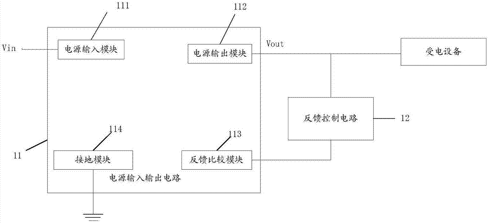
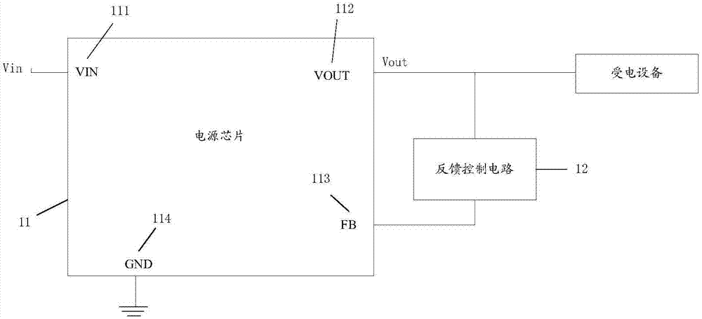
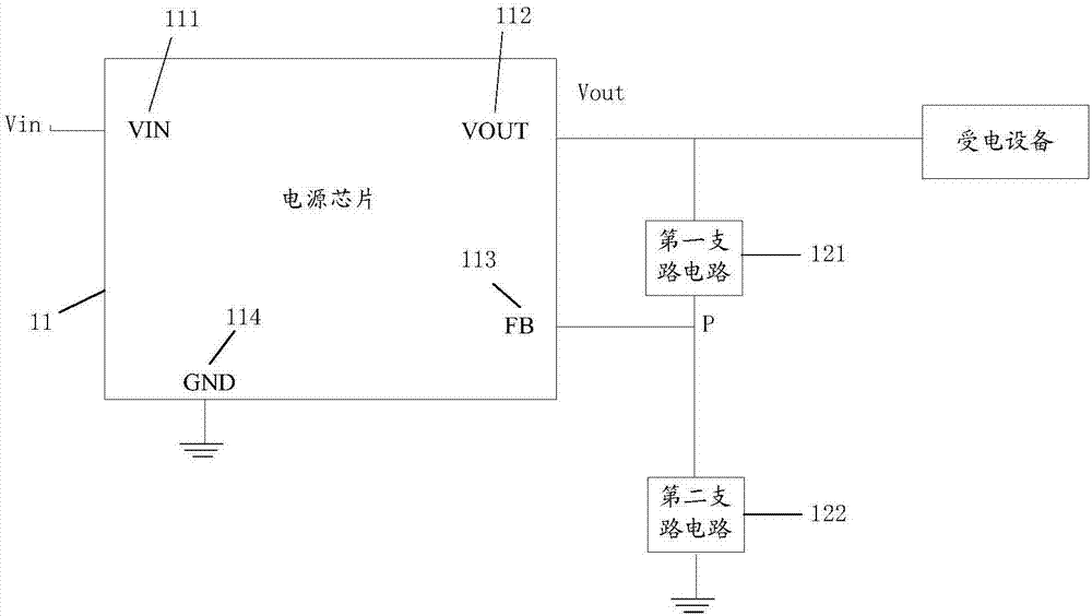
[0035] see figure 1 , this embodiment shows a power supply circuit, the power supply circuit includes a feedback control circuit, one end of the feedback control circuit is connected to the power output module of the power input and output circuit, and the feedback comparison module can be fed back according to the output voltage of the power output module Input the corresponding feedback voltage, wherein, the feedback voltage and the output voltage satisfy one of at least one preset calculation formula, and the relationship between the feedback voltage and the output voltage is realized by the feedback control circuit, so through the feedback control circuit, the power output module outputs The voltage can have a variety of different output values ​​to meet the needs of the current device working in different power consumption modes.

[0036] The power circuit of this embodiment includes a power input and output circuit 11 and a feedback control circuit 12. The power input an...

Embodiment 2

[0062] see Figure 9 , this embodiment shows a voltage output method, including:

[0063] S901. The feedback control circuit inputs the feedback voltage to the feedback comparison module of the power input and output circuit according to the output voltage of the power output module in the power input and output circuit; one end of the feedback control circuit is connected to the power output module, and the other end is connected to the feedback comparison module; the feedback voltage is connected to the feedback comparison module. The output voltage satisfies one of at least one preset calculation formula;

[0064] S902. The feedback comparison module compares the feedback voltage with a preset reference voltage;

[0065]S903. When the feedback voltage is different from the preset reference voltage, the power input and output circuit correspondingly adjusts the output voltage of the power output module until the feedback voltage is the same as the preset reference voltage. ...


PUM


Abstract

The invention discloses a power supply circuit, a terminal, and a voltage output method. The power supply circuit includes a power supply input output circuit and a feedback control circuit; the power supply input output circuit includes a power supply input module, a power supply output module, a feedback comparison module, and a grounding module; the power supply output module is connected to a power receiving device; one end of the feedback control circuit is connected to the power supply output module, and the other end of the feedback control circuit is connected to the feedback comparison module; the feedback control circuit is used for inputting the corresponding feedback voltage to the feedback comparison module according to the output voltage of the power supply output module; the feedback voltage and the output voltage meet at least one preset calculation formula, the feedback comparison module compares the feedback voltage and the preset reference voltage, and when the comparison result is different, the power supply output module adjusts the output voltage till the feedback voltage is identical to the reference voltage. According to the invention, the feedback control circuit is improved so as to achieve output of voltages at different levels, and the feedback control circuit is simple in design, is easy to achieve, can avoid an additional power supply input output circuit, and can save the cost.

Description

technical field [0001] The invention relates to the field of electronic technology, in particular to a power supply circuit, a terminal and a voltage output method. Background technique [0002] In the current circuit design of the motherboard of electronic products, there are two common circuits for generating electricity: BUCK circuit and LDO circuit. These two circuits have one thing in common, the voltage value of the feedback PIN pin (FBPIN pin) of the chip that they generate electricity It is a fixed value V1. The feedback circuit divides the output power supply voltage through two voltage divider resistors and then feeds it back to the feedback pin of the chip, so as to ensure that the output voltage is maintained at a stable voltage value. [0003] With the development of technology, electronic products, especially mobile terminal electronic products, have higher and higher requirements on resource utilization. In order to reduce the power consumption of electronic p...

Claims


Application Information

Patent Timeline
Patent Type & Authority Applications(China)
IPC IPC(8): G05F1/56
CPCG05F1/56
Inventor 曾文兴
Owner NUBIA TECHNOLOGY CO LTD
Learn More