Luminous decay resistant furnace

A light decay furnace and light decay technology, applied in sustainable manufacturing/processing, electrical components, climate sustainability, etc., can solve problems such as weak passivation, and achieve obvious effects, high output power, and suppression of light decay. Effect

Active Publication Date: 2017-08-15
FOLUNGWIN AUTOMATIC EQUIP CO LTD
View PDF6 Cites 8 Cited by
  • Summary
  • Abstract
  • Description
  • Claims
  • Application Information

AI Technical Summary

Problems solved by technology

Regardless of whether it is deposition of silicon nitride film or hydrogen plasma treatment, the problem with these methods is that hydrogen can only be introduced into the near-surface layer of the silicon crystal (usually less than a few microns), but cannot introduce high-concentration hydrogen atoms into the matrix, so Hydrogen atoms have a very weak passivation effect on impurities and defects inside the solar cell matrix

Method used


Image

  • Luminous decay resistant furnace
  • Luminous decay resistant furnace
  • Luminous decay resistant furnace

Examples


Embodiment Construction

[0041] The present invention will be further described below according to the accompanying drawings and specific embodiments, but the embodiments of the present invention are not limited thereto.

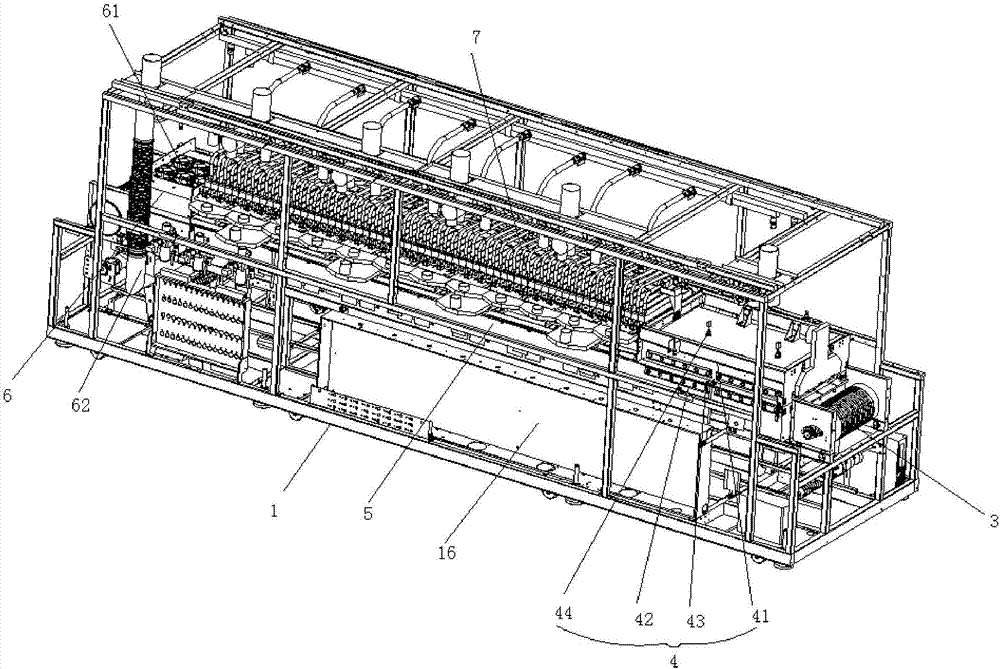
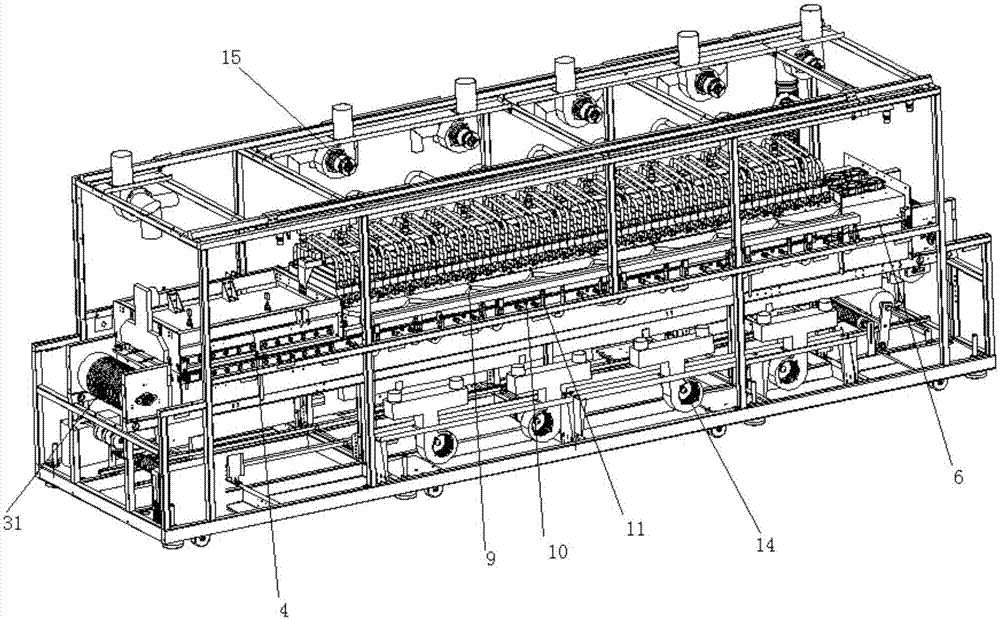
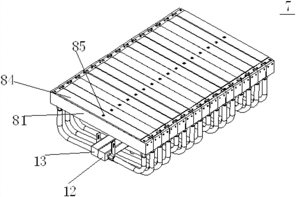
[0042] Such as figure 1 , figure 2 , image 3 , Figure 4 , Figure 5 , Figure 6 , Figure 7 and Figure 8 As shown, an anti-light decay furnace includes a furnace support 1 and a plurality of constant current sources 2. The furnace support 1 is provided with a conveying device 3 for circularly conveying silicon wafers. The furnace support 1 is along the feeding end of the conveying device 3 to the discharge A preheating zone 4, a lighting zone 5 and a cooling zone 6 are provided in sequence at the end of the lighting zone 5, and several groups of LED lighting modules 7 arranged side by side are arranged directly above the lighting zone 5, and each group of LED lighting modules 7 is composed of multiple water-cooled It consists of functioning LED light bars 8, and each LED ...


PUM


Abstract

The invention discloses a luminous decay resistant furnace, which comprises a furnace bracket and a plurality of constant-current sources, wherein a conveying device for conveying wafers circularly is arranged on the furnace bracket, the furnace bracket is sequentially provided with a preheating region, a luminous region and a cooling region along a direction from a charging end to a discharging end of the conveying device, a plurality of groups of LED lamp luminous modules which are arranged side by side are positioned just above the luminous region, each group of LED lamp luminous modules is composed of a plurality of LED lamp strips having a water cooling function, and each LED lamp strip is controlled by one of the constant-current sources independently. According to the luminous decay resistant furnace, one constant-current source controls one LED lamp strip independently, so that the LED lamp strip has ultra-high luminous intensity, the heating temperature thereof can be controlled, and the LED lamp strip operates at constant temperature. In the process that the wafers enter the luminous decay resistant furnace, the wafers are subjected to strong light exposure by means of the plurality of groups of LED lamp luminous modules, and the hydrogen passivation effect of the wafers is obvious.

Description

technical field [0001] The invention relates to the field of hydrogen passivation of photovoltaic cells, in particular to an anti-light decay furnace. Background technique [0002] Solar power technology is currently one of the most important renewable energy technologies. At present, the cost of solar power generation is still higher than that of traditional energy sources, which restricts its large-scale application. For this reason, the industrial and scientific circles have been devoting themselves to improving the photoelectric conversion efficiency of solar cells and reducing the manufacturing cost of solar cells. [0003] Solar power generation is based on the photovoltaic effect of semiconductor materials. The P-type semiconductor and the N-type semiconductor contact to form a PN junction, which generates a strong internal electric field. When the light irradiates the semiconductor, the electrons and holes generated by the excitation are separated by the electric ...

Claims


Application Information

Patent Timeline
Patent Type & Authority Applications(China)
IPC IPC(8): H01L31/18
CPCH01L31/1868Y02P70/50
Inventor 苏金财王军涛何凤涛
Owner FOLUNGWIN AUTOMATIC EQUIP CO LTD
Why Eureka
Try Eureka