
Oil vapor recovery system

A technology of oil and gas recovery system and absorption system, applied in gas treatment, membrane technology, dispersed particle separation, etc., can solve the problems of high energy consumption, high process cost, high failure rate, and achieve the effect of realizing recycling and saving process cost.

Pending Publication Date: 2017-08-18
BAY ENVIRONMENTAL TECH BEIJING
View PDF9 Cites 3 Cited by
  • Summary
  • Abstract
  • Description
  • Claims
  • Application Information

AI Technical Summary

Problems solved by technology

Among them, in the absorption method, it is usually necessary to provide a large amount of special absorbent, which makes the process cost very high, and it is impossible to continue to realize oil and gas recovery without special absorbent
Other oil and gas recovery methods, such as condensation, have high energy consumption, high failure rate, poor stability, and more complex systems

Method used


Image

  • Oil vapor recovery system

Examples


Embodiment Construction

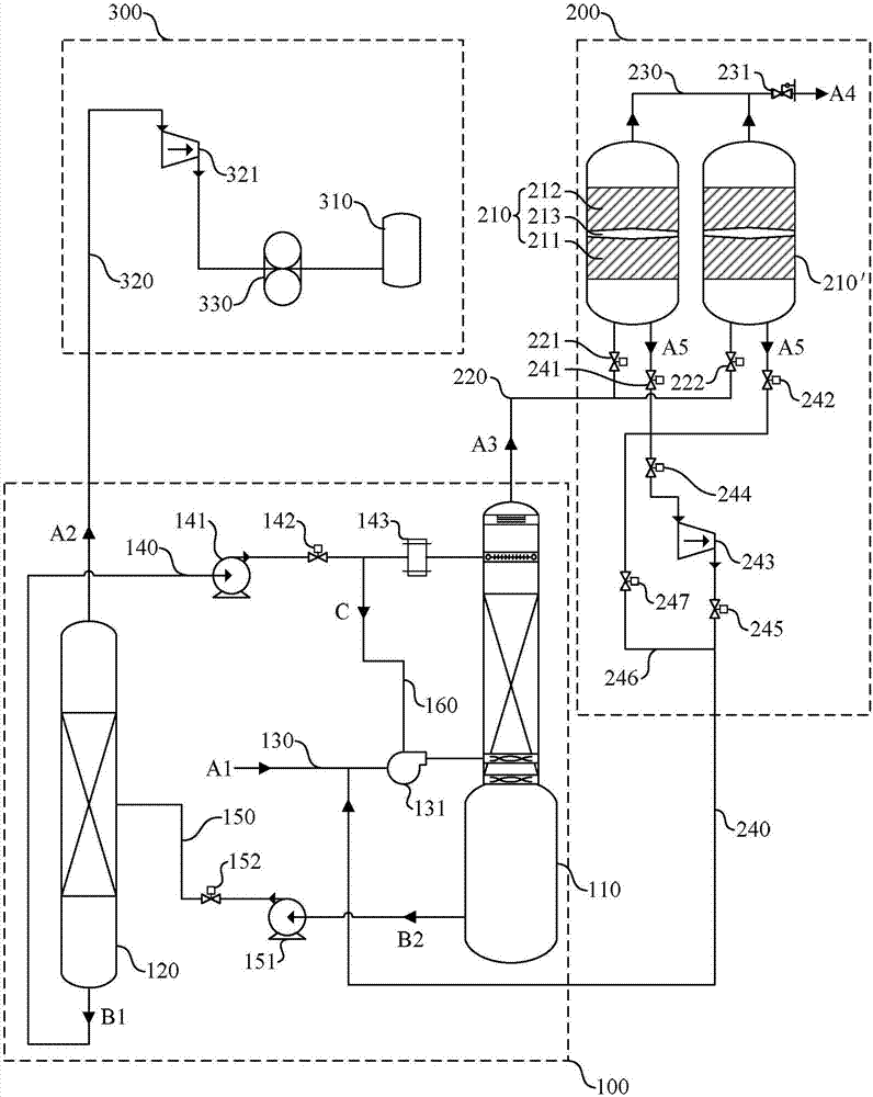
[0031] Hereinafter, the present invention will be described in more detail with reference to the accompanying drawings. For the sake of clarity, various parts in the drawings have not been drawn to scale. Also, some well-known parts may not be shown. There are many specific details of the invention described below, but the invention may be practiced without these specific details, as will be understood by those skilled in the art.

[0032] It should be understood that when describing the structure of a component, when a layer or a region is referred to as being “on” or “over” another layer or another region, it may mean being directly on another layer or another region, or Other layers or regions are also included between it and another layer or another region. And, if the part is turned over, the layer, one region, will be "below" or "beneath" the other layer, another region.

[0033] figure 1 A schematic diagram showing an oil vapor recovery system according to an embodi...


PUM


Abstract

The invention discloses an oil vapor recovery system. The oil vapor recovery system comprises an absorption system. The absorption system comprises an absorption tower, a regeneration tower, a first pipeline, a second pipeline and a third pipeline, wherein the first pipeline is connected to the absorption tower, and the second pipeline and the third pipeline are connected between the absorption tower and the regeneration tower. The first pipeline supplies oil vapor and inputs the same into the absorption tower, the regeneration tower supplies an absorbent, the absorbent is inputted into the absorption tower via the second pipeline and flows back to the regeneration tower via the third pipeline after interacting with the oil vapor, and the regeneration tower separates the backflow absorbent into a regenerative absorbent and recovered oil vapor. The oil vapor recovery system has the advantages that the regeneration tower arranged in the oil vapor recovery system separates the backflow absorbent into the regenerative absorbent and the recovered oil vapor, so that cyclic utilization of the absorbent is achieved, the oil vapor recovery system can run continuously in shortage of the absorbent, and technological cost is saved.

Description

technical field [0001] The invention relates to the field of oil and gas utilization, and more specifically, to an oil and gas recovery system. Background technique [0002] Because oil products contain a large amount of light hydrocarbon components, they are highly volatile, and oil and gas volatilization will inevitably occur during storage and transfer. The volatilization of oil and gas will not only cause a large loss of oil products, but also the volatilized oil and gas will pollute the environment. With the continuous implementation of energy saving and emission reduction strategies worldwide, the control of oil volatilization is becoming more and more important. However, at present, it is difficult to fundamentally control the volatilization of oil products. As a technology that can collect and reuse oil and gas, oil and gas recovery technology has become more practical. [0003] The existing oil and gas recovery methods are mainly absorption method, adsorption meth...

Claims


Application Information

Patent Timeline
IPC IPC(8): B01D53/18B01D53/04
CPCB01D53/0423B01D53/1418B01D53/1425B01D53/1487B01D53/18B01D2252/20B01D2259/402B01D2259/40083B01D2259/4516B01D2259/4148
Inventor 刘国强
Owner BAY ENVIRONMENTAL TECH BEIJING
Learn More